


Operation of Oven Burners & OvenAdjustments
9. Electric Ignition Burners
Operation of electric igniters should be checked after range and
supply line connectors have been carefully checked for leaks and
range has been connected to electric power.
The oven burner is equipped with an electric control system as
well as an electric oven burner igniter. If your model is equipped
with a waist-high broil burner, it will also have an electric burner
igniter. These control systems require no adjustment. When the
oven is set to operate, current will flow to the igniter. It will "glow"
similar to a light bulb. When the igniter has reached a temperature
sufficient to ignite gas, the electrically controlled oven valve will
open and flame will appear at the oven burner. There is a time
lapse from 30 to 60 seconds after the thermostat is turned ON
before the flame appears at the oven burner. When the oven
reaches the dial setting, the glowing igniter will go off. The burner
flame will go "out" in 20 to 30 seconds after the igniter goes "OFF."
To maintain any given oven temperature, this cycle will continue
as long as the dial (or display) is set to operate.
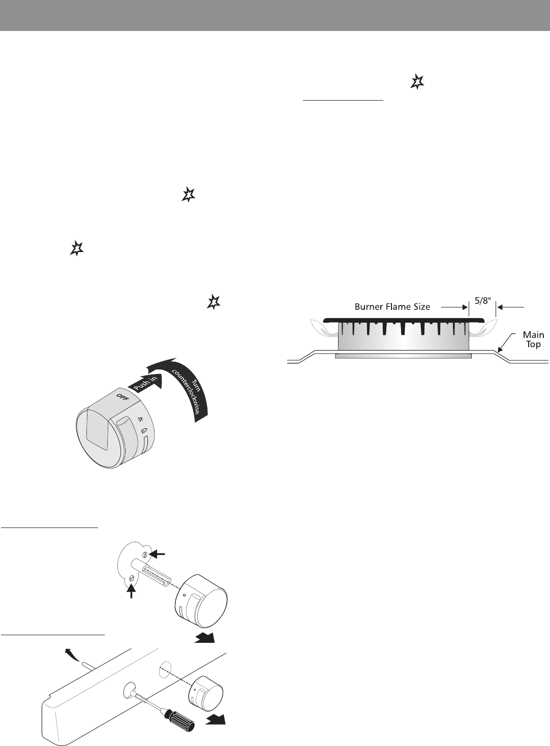
Adjust flame until you can quickly turn knob from LITE to
LOWEST POSITION without extinguishing the flame. Flame
should be as small as possible without going out.
Note: Air mixture adjustment is not required on surface
burners.
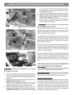
8. Adjust the "LOW" Setting of Surface Burner
Valve (Linear Flow Valves):
Fig. 1
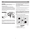
7. Electric Ignition Surface Burners
Operation of electric igniters should be checked after range and
supply line connectors have been carefully checked for leaks and
range has been connected to electric power.
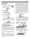
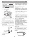
a. To check for proper lighting, push in and turn a surface
burner knob counterclockwise to the
(lite) position.
You will hear the igniter sparking (See Fig. 1).
b. The surface burner should light when gas is available to
the top burner. Purge air from supply lines by leaving
knob in the
(lite) position until burner ignites. Each
burner should light within four (4) seconds in normal
operation after air has been purged from supply lines.
c. Visually check that burner has lit. Once the burner lights,
the control knob should be turned out of the
(lite)
position.
d. There are separate electrodes (igniters) for each burner.
Try each knob separately until all burner valves have been
checked.
REMEMBER — DO NOT ALLOW SPILLS, FOOD,
CLEANING AGENTS OR ANY OTHER MATERIAL TO
ENTER THE GAS ORIFICE HOLDER OPENING.
Always
keep the Burner Caps and Burner Heads in place whenever
the surface burners are in use.
Fig. 2
Test to verify if “LO or LOW” setting should be adjusted (right front
position ONLY):
a. Push in and turn knob to
(lite) until burner ignites.
b.
Push in and quickly turn knob to LOWEST POSITION.
c. If burner goes out, reset control to OFF.
d. Remove the burner control knob.
e. Use a thin-bladed screwdriver and adjust the inner burner
flame size with the right-hand set screw (See Fig. 2). Adjust
the outer burner flame size with the lower set screw (See Fig.
2). Turn counterclockwise to increase flame size. Turn
clockwise to decrease flame size.
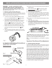
Test to verify if “LO or LOW” setting should be adjusted (all other
positions):
a. Follow steps a thru d above.
b. Insert a thin-bladed screwdriver into the hollow valve stem
and engage the slotted screw inside (Fig. 3) . Flame size can
be increased or decreased with the turn of the screw. Turn
counterclockwise to increase flame size. Turn clockwise to
decrease flame size.
Inner burner flame
adjustment screw
Outer burner flame
adjustment screw
Right-hand burner only
All other surface burners
Fig. 3
INSTALLATION INSTRUCTIONS FOR FREESTANDING GAS RANGE
7