


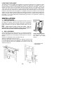


LOCATION OF APPLIANCE
This appliance must not be installed in a bed-sitting room of volume less than 20m³ or in a bathroom shower
room or garage. It is essential that the appliance is positioned as stated below. The appliance must be a
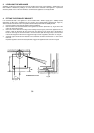
minimum of 20mm from the rear wall (note that this dimension is provided by the inlet elbow). Shelves, wall
cabinets and cooker hoods must not be fitted closer than 500mm to the top of the grill canopy or within
100mm of the sides of the grill. Curtains must not be fitted immediately behind the appliance or within 200mm
of the sides of the grill. If fitted next to or between two base units a minimum space of 1mm must be left
between the units and the sides of the appliance. The hotplate must be set to a minimum of 7mm above the
adjacent units (note that the levelling feet fitted to the appliance will achieve a nominal height to hotplate level
of 907mm -5+13mm). Base units not meeting the above conditions must be a minimum of 100mm away from
the hotplate. L.P.G. cookers MUST NOT be installed below ground level, i.e in a basement, or aboard any
boat, yacht or other vessel.
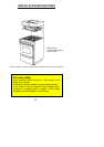
INSTALLATION
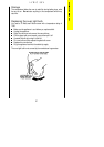
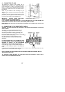
1. PARTS REQUIRED
The loose hotplate parts are packed in the polystyrene fitment on the top of
the hotplate. The grill pan, grill pan handle, fixing screws and splashplate
fixing screws can be found in the furniture pack which is located in the
bottom compartment. The grill pan requires assembly before use (see
Fig.1).
NOTE: Taptite screws are used to secure the handle. These are
thread forming screws and sufficient pressure must be applied to
allow the screws to produce a thread in the plunged holes.
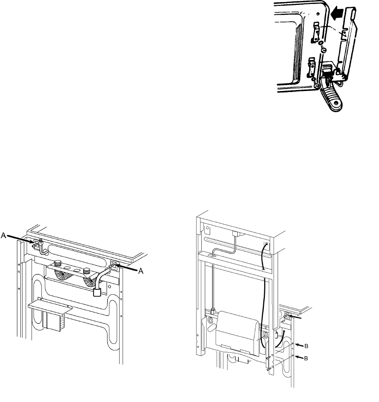
2. GRILL ASSEMBLY
The two splashplate screws marked A (see Fig. 1a) should be screwed into
the back of the appliance about halfway in. Engage the keyhole slots in the
splashback behind the two screws taking care not to trap the H.T. wire (see
Fig. 1b).
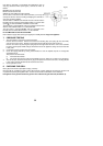
Insert the four splashplate screws marked B (see Fig. 1b).
Tighten 6 off splashplate screws (see Fig.1b).
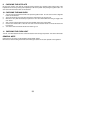
Connect the grill supply union at the back of the appliance and pull the grill
H.T. lead through the opening in the splashplate. Feed lead through the hole
in the top right hand side of the splashplate and connect on to the grill
electrode, (see Fig.1b)
Grill Pan Handle Assembly:
Assemble grill pan (see Fig.1)
and secure four screws
provided.
Fig.1
35
Fig.1b
Fig.1a
Connect grill H.T. lead
to grill electrode