


INSTALLATION INSTRUCTIONS
Page 6 62.9680.01_UL
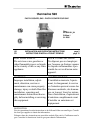
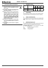
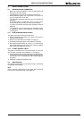
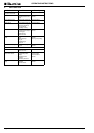
1.4 SIDEWALL (D)
The assembly kit contains two of each of the following:
hexagonal screws M8x25 (1 / Fig.1), bolts with retaining rings
(2 / Fig.1), mounting links (3 / Fig.1), hexagonal screws M8x16
with serrated washers and hexagonal nuts M8, hexagonal
screws M5 with serrated washers (4 / Fig.2)
and a fastening angle (5 / Fig.2).
D Insert the bolts with the retaining rings (2 / Fig.1a) from out-
side into the guide in the sidewall.
D Keeping the screw (1 / Fig.1a) loose, turn it until it is
approximately 5 mm deep in the pre-assembled caged
nuts in the sidewall.
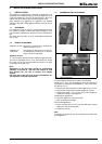
D Attach the fastening angle (5 / Fig.2b) to the bottom of the
frame using the screws, serrated washers and nuts.
D (4 / Fig.2).
D Position the sidewall and screw it on from below using two
hexagonal screws and the serrated washers.
D Fit the mounting link (3 / Fig.1b) into the inside of the appli-
ance's connecting plate.
D Align the sidewall and firmly tighten all screws.
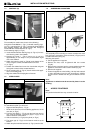
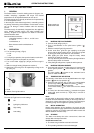
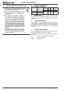
1.5 STEEL PLINTH
To assemble the plinth you will need:
• Right and left side plinth (1 / Fig.3).
• Plinth for the front and, for free-standing appliances, for the
rear also (2 / Fig.3).
D Push the side plinth (1 / Fig.3) onto the legs from front to
rear using the fastener. The larger gap (b / Fig.3) on the
fastener must be at the bottom.
D Affix the fasteners (3 / Fig.3) to the plinth (2 / Fig.3).
D The larger gap (b / Fig.3) on the fastener must be at the
bottom.
D Attach the plinth with the fasteners (3 / Fig.3) onto the feet.
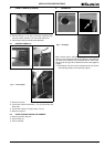
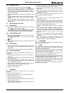
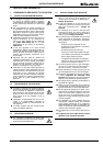
1.6 ASSEMBLING ON CASTORS
The assembly kit for mounting on castors contains two cross
bars (2/Fig.4a) each with a fixed rear wheel (1/Fig.4a) and a
turnable front wheel (3/Fig.4a).
Mounting the castors:
D Put the appliance on supports.
D Remove the feet; each is tightened with four screws
(Fig.4b).
D Bring the two cross bars into the correct position below the
appliance and fasten it with 8 screws arrows (Fig.4a).
D Remove the supports.
D Fasten the appliance to the building. Use the hole to attach
a chain descending from the wall (arrow/Fig.4c). Making
sure the chain is shorter than the gas and electric connec-
tions.
Note:
Appliances on wheels must be secured by fasten it to the
building.
2. ACCESS TO INTERIOR
Note:
Only authorized technicians may access the interior.
a
b
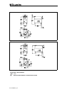
Fig.2 Assemblage of sidewall
a
b
Fig. 3 Plinth assembly
1
()
(5)
(4)
1
(3c)
1
()
(5)
(4)
(1)
(2)
(3)
b
b
1
(3c)
(1)
(2)
(3)
a
b
c
Fig.4 Assemblage on castors
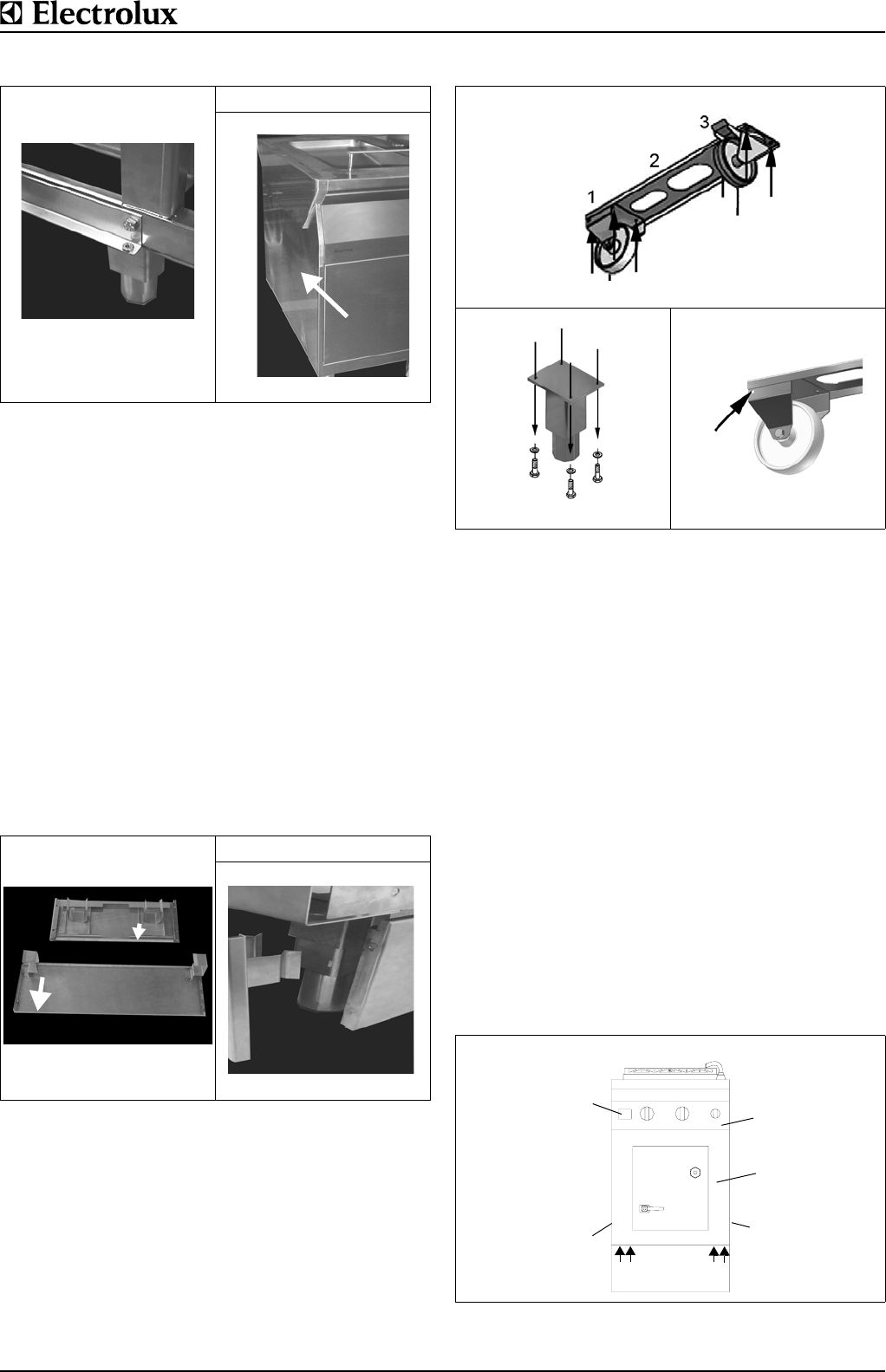
Fig. 5 General view
1
()
(5)
(4)
1
(3c)
1
(3c)
11
D
D
B
E
C
11