


electrolux electrolux
electrolux electrolux
electrolux installation
1919
1919
19
GB
InstallationInstallation
InstallationInstallation
Installation
Make surMake sur
Make surMake sur
Make sur
e that the cooker hood is disconnected fre that the cooker hood is disconnected fr
e that the cooker hood is disconnected fre that the cooker hood is disconnected fr
e that the cooker hood is disconnected fr
om the power supply beforom the power supply befor
om the power supply beforom the power supply befor
om the power supply befor
ee
ee
e
carrying out the installation.carrying out the installation.
carrying out the installation.carrying out the installation.
carrying out the installation.
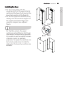
The cooker hood comes with fixing plugs which are suitable for use with most
walls/ceilings. Nevertheless, you should ask a qualified technician to assess the
suitability of the materials in accordance with the type of wall/ceiling. The wall/
ceiling must be sufficiently sturdy so as to support the weight of the cooker hood.
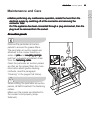
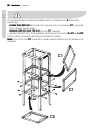
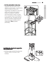
Remove the perimeter air suction panels and the grease filters.
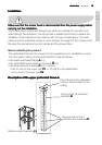
Before installing the product:
The perforated frame for the cooker hood is supplied prior to installation in parts.
The main parts making up the perforated frame are as follows:
• the upper perforated frame
AA
AA
A (x1)
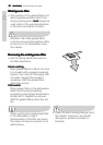
• the perforated frame extension brackets
BB
BB
B (x4)
• the reinforcement brackets
CC
CC
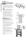
C (x3), of which:
2 are for use on the upper part
C1 - C1 -
C1 - C1 -
C1 - 1 of which is pre-assembled
1 is for use on the lower part
C2C2
C2C2
C2
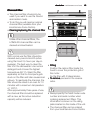
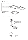
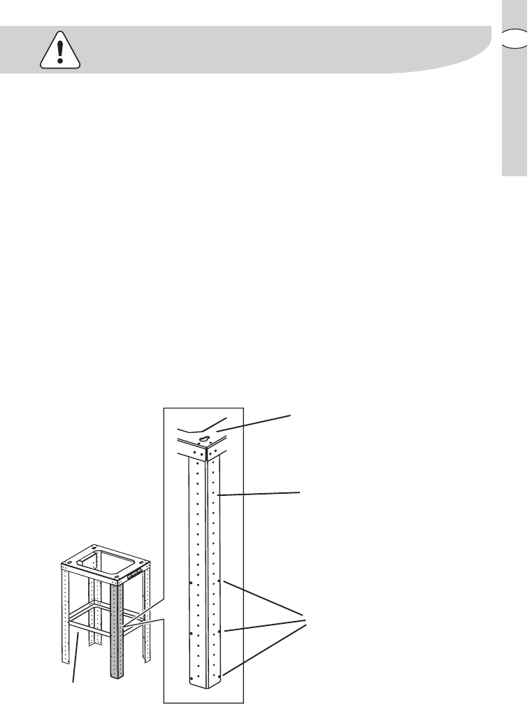
Description of the upper perforated frame A:Description of the upper perforated frame A:
Description of the upper perforated frame A:Description of the upper perforated frame A:
Description of the upper perforated frame A:
Point at which the perforated
frame is fixed/hooked to the
ceiling
Fixing points for extension
brackets
BB
BB
B
Fixing points for the 2
reinforcement brackets
C1C1
C1C1
C1
Reinforcement brackets
C1C1
C1C1
C1