


2424
2424
24
electr electr
electr electr
electr
oluxolux
oluxolux
olux installation
GB
Installing the structural support toInstalling the structural support to
Installing the structural support toInstalling the structural support to
Installing the structural support to
the ceilingthe ceiling
the ceilingthe ceiling
the ceiling
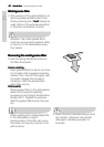
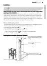
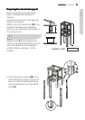
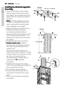
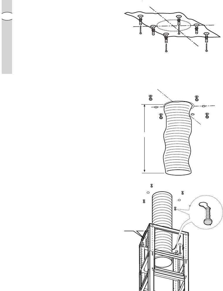
• Place the template on the ceiling
directly above the hob (the centre
and sides of the template should be
aligned with the centre and sides of
the hob).
Note: Note:
Note: Note:
Note: The side displaying the text
“FRONT” corresponds to the side
which will house the control panel
once installation is complete.
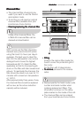
• Make the holes as indicated on the
template (6 holes for 6 screw
anchors) and partially tighten 4
screws into the screw anchors in the
corners (leave approximately 1 cm
between the head of the screw and
the ceiling).
• Prepare the electrical connection.
•
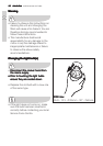
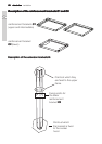
Ducted version only:Ducted version only:
Ducted version only:Ducted version only:
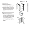
Ducted version only: Install an
exhaust tube long enough to reach
the outlet ring located above the
cooker hood.
The tube should be fitted to the
ceiling as an exhaust system to expel
fumes outside; the visible part should
be 180 mm shorter than the
structural support (please refer to
measurement
EE
EE
E calculated
previously).
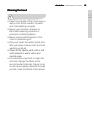
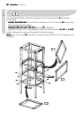
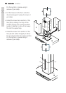
• Install the structure to the ceiling,
onto the 4 pre-tightened screws and
then screw them in firmly.
• Fix it in place using 2 screws.
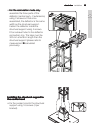
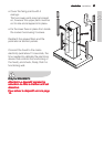
• Connect the exhaust tube to the
connection ring above the cooker
hood.
• Carry out the necessary electrical
connection.
X 4!
2 x
Ø6 x 70
FRONT
6 x Ø 10 + 4 x Ø 6x70
SX
DX
FRONT
E (mm)-180