


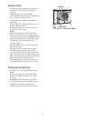


Installation
Fig. 9
I
I
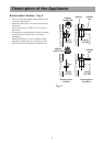
Ø 2,5mm x 6mm max
6mm
N3
K
J
L
L
M1
M1
M2
M2
Fig. 10
Fig. 11
Mounting accessories included
1 deflector
1 coupling ring Ø 100 mm (EFI 635) or Ø 120 mm
(EFI 640)
2 plastic washers for the spacer
4 wall dowels (screw anchors)
2 screws 5 x 45 with cylindrical heads for use on
walls (lower fixing)
2 screws 5 x 45 countersunk for wall use (fixing
the hooks)
2 hooks
1 Allen wrench
1 screw 2.9 x 9.5 (ONLY EFI 635 - to affix the
deflector on the outlet hole)
2 screws 3.5 x 9.5 (to affix the spacer to the
cooker hood)
2 screws 4.2 x 35 (ONLY EFI 635 - to fix the
hood to the top of a wall cabinet)
2 screws 2,9 x 13 (ONLY EFI 640 - to fix the
deflector to the hood or to the top of a wall
cabinet)
4 screws 4.5 x 16 (to affix the cooker hood
sideways)
8 screws 4.5 x 13 (to affix a wooden panel to the
cabinet door).
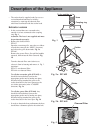
Fixing a furniture door to the
visor
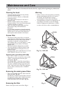
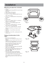
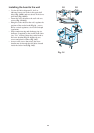
Remove the extraction grille.
Remove the visor (freeing the locking releases
I-Fig.9).
Apply the drill holes diagram N3 on the rear of
the furniture door (Fig. 10,J-the arrow on the
diagram should face the upper border of the
furniture door), perform blind holes as
indicated (K-Fig. 10).
Place the visor over the furniture door and affix
with 8 screws (Fig. 10,L).
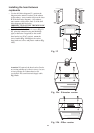
Refit the cover on the cooker hood firstly in the
upper track (Fig. 11-M1), then in the lower
track (Fig. 11-M2).
Where the cooker hood is provided with
revolving locking releases these should be
turned in the opposite direction of the release to
ensure that the visor is not unintentionally
released during normal use of the cooker hood.
Fig. 9.