


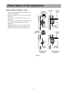
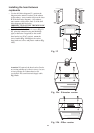


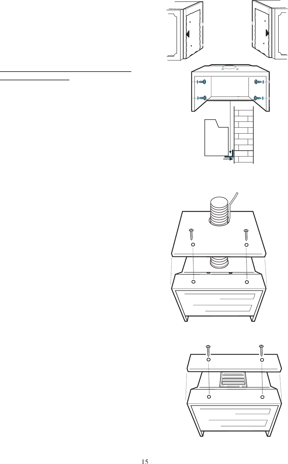
Installing the hood between
cupboards
Use the drill holes diagram N2, position the
diagram on the anterior borders of the cabinet
(right cabinet must remain visible on the letter
B of the drill holes diagram) (left cabinet
must remain visible on the letter C of the drill
holes diagram) drill the holes
IRRESPECTIVE OF THE THICKNESS OF
THE CABINET DOOR.
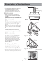
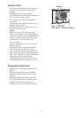
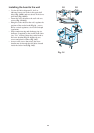
Fasten the cooker hood with 4 screws (Fig. 12
,P), place the connection ring and discharge
pipe (or deflector if supplied) to the cooker
hood outlet (see Use section), mount the
lower bracket (Fig. 12-13,Q) to the cooker
hood with two screws and plastic washers (Fig.
13,T).
Attention! If required, the hood can be fixed to
an existing cabinet top with two screws, be sure
to leave passage for exhaust hose (or for
recycled air flow) and electrical supply cable.
Fig. 13a-b.
P
P
Q
N2
B
N2
C
Fig. 12
Fig. 13a - Extractor version
Fig. 13b - Filter version