


Instructions for the installer
10
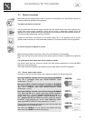
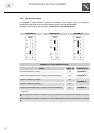
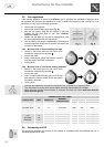
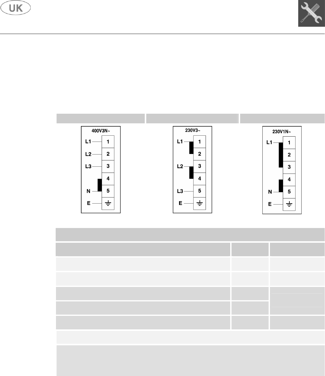
3.3.2 Type of power supply
It is possible to obtain different connections according to the voltage, simply by moving the
unconnected cable ends on the terminal board as shown in the following diagrams.
According to the model, consult the table "C
ONNECTION TO THE TERMINAL BOARD".
DIAGRAM “A” DIAGRAM “B” DIAGRAM “C”
CONNECTION TO THE TERMINAL BOARD
MODEL POWER kW POWER SUPPLY
COOKER 6 BURNERS (1 OVEN) 2,9
DIAGRAM “C”
COOKER VITROCERAMIC HOB (1 OVEN) (5 HEATING ELEMENTS) 12,7
DIAGRAM “A”
COOKER 6 BURNERS (2 OVENS) 3,9
COOKER 4 BURNERS (2 OVENS) + T 6,3
DIAGRAM “C”
COOKER VITROCERAMIC HOB (2 OVENS) (5 HEATING ELEMENTS) 13,7
DIAGRAM “A”
T = FRY-TOP
MODELS CONNECTED ACCORDING TO DIAGRAM "A" CAN BE COMMUTATED BY THE INSTALLER ACCORDING TO DIAGRAM
"B".
MODELS CONNECTED ACCORDING TO DIAGRAM "C" CAN BE COMMUTATED BY THE INSTALLER ACCORDING TO DIAGRAM
"A".