


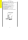
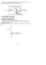
INSTALLATION Flexible Pipe Installation.
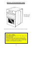
FITTING THE APPLIANCE AND CABINET
It is recommended that a
3
/8" 1100mm long angle bayonet flexible hose (B.F.S.) and a ½" straight socket
(B.F.S.) be used for the installation. However any approved hose of the correct length can be used.
IMPORTANT: Flexible tubing used must comply with BS 669 current editions. L.P.G. flexible connections
must be of a type suitable for L.P.G. and capable of operation up to 50mbar and carry a red stripe, band or
label.
NOTE: Only liquid sealants can be used in threaded gas connections. Do not use P.T.F.E. tape.
1 Make suitable arrangements for gas and electric supplies into the installation site. Preferably a junction
box or a 3 pin earthed socket should be situated at the back of the cabinet below the oven.
2 The electrical connection to the appliance is at the rear bottom right hand side; the junction box or socket
should be positioned accordingly.
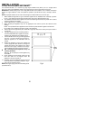
3 Fit the cabinet as Fig.1, make sure that it is level.
4 When unpacking the appliance keep it on it's polystyrene base until it is put into the cabinet to avoid
damage.
NOTE: It is imperative that the appliance is left in the base to protect both the appliance and the floor.
Do not allow young children to play with any part of the packaging.
5 Remove the oven and grill doors (See section B on page 43). Remove the fascia panel (See section A
on page 42).
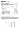
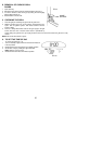
6 If the gas supply bayonet and wall fixing bracket
are to be located behind the appliance it must be
located in the shaded area as indicated in Fig.3.
7 Connect flexible hose to the gas inlet supply block
see Fig.3. The hose should be long enough to
allow the appliance to be withdrawn from the
cabinet.
8 Position the appliance in front of the cabinet and
run the supply cable (See Section 2) through the
cabinet and connect to the junction box or socket.
Ensure that the supply is isolated at this stage.
Connect flexible hose to the bayonet connector.
N.B. Two people will be required to carry out
the lifting procedure.
Warning: Do not attempt to lift this appliance by
the handles.
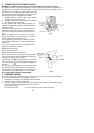
9 Lift the appliance into the cabinet making sure the
hose and cable are not trapped. Push the
appliance as far back as it will go.
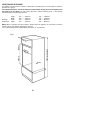
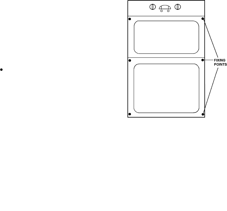
10 Centralise and fix the appliance using the six wood
screws provided, in the position indicated in Fig.2.
11 Carry out gas soundness check.
NOTE: Check gas supply pressure before fitting fascia
(See SECTION 3).
39
Fig.2