


INSTALLATION Solid Pipe Installation
FITTING THE APPLIANCE AND CABINET.
1 Make suitable arrangements for gas and electrical supplies into the installation site. Preferably a junction
box or a 3 pin earthed socket should be situated at the back of the cabinet below the oven.
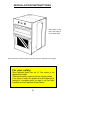
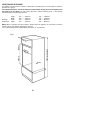
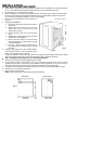
2 Fit cabinet as Fig. 1, making sure that it is level.
3 When unpacking the oven keep it on it's polystyrene base until it is put into the cabinet to avoid damage.
NOTE: It is imperative that the appliance is left in the base to protect both the appliance and the floor.
Do not allow young children to play with any part of the packaging.
4 Remove the oven and grill doors. (See section B on
page 43).
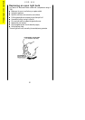
5 Solid gas pipe installation:
i) Remove the fascia control panel (See section A
on page 43).
ii) Slacken and remove the union nut on the gas
supply elbow on the right hand side of the
control panel. See Fig.7.
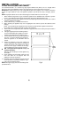
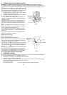
iii) Remove the two screws on the gas inlet block
Fig.3.
iv) Withdraw the gas inlet block and pipe assembly
from the back of the appliance
v) Remove the union elbow from the inlet block
and pipe assembly. The elbow will be required
in the final installation.
vi) The union elbow should be connected to the
gas supply pipe via a standard ¼"B.S.P. straight
connector.
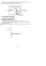
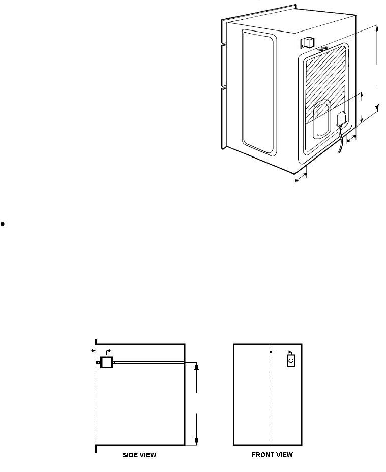
6 Install the gas supply pipe on site complete with the
union elbow (See Fig.4). Note the orientation of the
elbow, the connection must be upwards.
7 Position the appliance in front of the cabinet and run the supply cable (See Section 2) through the cabinet
and connect to the junction box or socket. Ensure that the supply is isolated at this stage.
N.B. Two people will be required to carry out the lifting procedure.
Warning: Do not attempt to lift this appliance by the handles.
8 Lift the appliance into the cabinet making sure the gas supply pipe enters the duct in the rear of the
appliance and the cable is not trapped by the appliance. Push the appliance as far back as it will go.
Ensure the supply pipe comes through the control panel and pull through any slack cable.
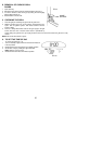
9 Centralise and fix the appliance to the cabinet using six wood screws in the position indicated in Fig.2.
10 Tighten the union nut into the supply elbow.
11 Carry out gas soundness check .
NOTE: Check supply pressure before fitting fascia (See Section 3).
40
795
FRONT VIEW
mm
SIDE VIEW
225
Fig.4
75
GAS INLET SUPPLY BLOCK
680
Fig.3
280
120
120