


- 12 -
INSTALLATION INSTRUCTIONS
OPERATING INSTRUCTION
READ AND SAVE THESE INSTRUCTIONS
GENERAL
• Carefully read the following important information regarding installation safety and main-
tenance. Keep this information booklet accessible for further consultations.
The appliance has been designed for use in the ducting version (air exhaust to the outside
– Fig.1).
INSTALLATION INSTRUCTIONS
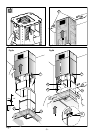
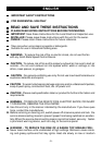
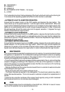
• Power Supply Connection
For connection to the power supply refer to the follows fig.16 :
BLACK = L line
WHITE = N neutral
GREEN / YELLOW = G ground
A double-pole switch properly rated must be installed to provide the range hood power
supply disconnection.
The appliance must be installed at a minimum height of 26 inches (66 cm) from an electric
cooker stove, or 30 inches (76 cm) from gas or combined cooker stoves. If a connection
ductwork composed of two parts is used, the upper part must be placed outside the lower
part. Do not connect the range hood exhaust duct air to the same duct air used to exhaust
hot air or fumes from other appliances other than electrical. Before proceeding with the
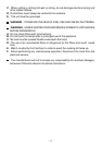
assembly operations, remove the anti-grease filter(s) (Fig.7) so that the unit is easier to
handle.
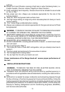
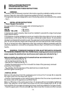
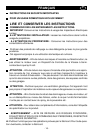
WARNING - TO REDUCE THE RISK OF FIRE, ELECTRIC SHOCK, OR INJURY
TO PERSONS, OBSERVE THE FOLLOWING: Before making electrical connections to
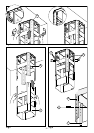
power supply, the electrical box must be secured in place as indicated in fig.1
Before installing the appliance fix the electrical box as indicated in fig.1
- Remove the central screw fig.1A.
- Lift the electrical plant box fig. 1B.
- Remove the 3 fixed screws fig.1C.
- Position the electrical box so it is in line with the holes of the previously removed
screws fig.1D and tighten.
- Pay attention that the tear tape of the electrical box is inside the slot
and then tighten screw fig.1E.
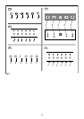
• INSTALLATION
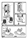
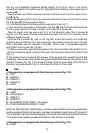
Remove the structure from the packaging and remove the 2 screws A to separate
the upper part from the lower part (fig.2).
- Position hole template on the ceiling paying attention that the arrow is positioned on
the same side as the appliance controls (Fig.3).
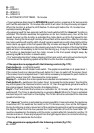
Make 4, Ø8 holes in the ceiling and drive in 3 screws without completely tightening
them. Pay attention not to insert the screw into the hole marked with an X on the
hole template (the screws and expansion plugs must be suitable for the type of wall).
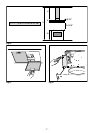
- Take the upper part of the structure B (fig.4) and insert the 3 slots onto the 3 screws