


Sequence of Operation
2
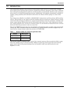
2.0 SEQUENCE OF OPERATION
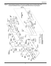
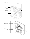
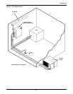
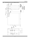
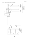
During normal operation, cold fluid flow from the chiller passes across the flow switch, through the
heat exchanger, through the pump bypass check valve, past the supply temperature sensor and out to
the load (see Figures 1 and 2). The standby cooling solenoid valve is closed (de-energized) and the
standby pump is off.
If the flow switch senses loss of flow, a time delay is initiated to prevent nuisance switchovers. After
the delay (see Table 2 below), the alarm panel indicates “standby pump on” and the common alarm
contacts close, while the standby pump is brought on to resume flow and the chiller pump is locked
out. This mode is locked in until the reset button is pressed.
Similarly, if the thermostat senses high fluid temperature, a time delay is initiated to prevent
nuisance switchovers. After the delay (see Table 2 below), the alarm panel indicates “standby cooling
on” and the common alarm contacts close, while the solenoid valve is energized to resume cooling.
This mode is locked in until the reset button is pressed.
Note that during normal operation, the auto/manual switches (see Figure 8) are set to “auto”. The
switch can be set to “manual” to force switchovers to standby pump and/or standby cooling for trouble-
shooting or maintenance.
Note that the “remote shutdown” function (see 4.0 - Installation) prevents emergency switchover
operation regardless of the status of other controls.
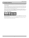
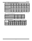
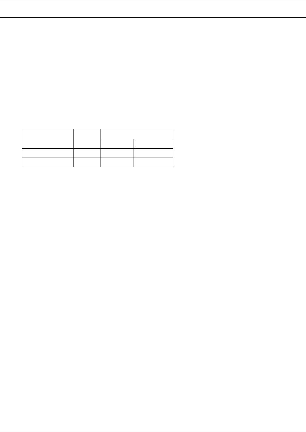
Table 2 Time delay settings
Condition Default
Delay (seconds)
Minimum Maximum
Loss of Flow 10 0 90
High Water Temp. 180 0 480