Reference Manual
00809-0100-4808, Rev CA
June 2008
Rosemount 3051N
2-2
FAILURE MODE ALARM Rosemount 3051N transmitters automatically and continuously perform
self-diagnostic routines. If the self-diagnostic routines detect a failure, the
transmitter drives its output outside of the normal saturation values. The
transmitter will drive its output low or high based on the position of the failure
mode alarm jumper. See Table 2-1 for failure mode and saturation output
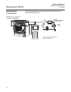
levels. To select alarm position, see “Configuring Transmitter Alarm and
Security Jumper Procedure” in Section 2.
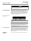
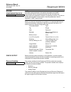
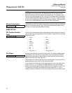
Table 2-1. Standard Alarm and
Saturation Values.
NOTE
You can alter the actual transmitter mA output values by performing an analog
output trim.
NOTE
When a transmitter is in an alarm condition, the hand-held HART
Communicator indicates the analog output the transmitter would drive if the
alarm condition did not exist. The transmitter will alarm high in the event of
failure if the alarm jumper is removed.
Alarm Level Verification Transmitters allow verification testing of alarm current levels. If you replace
the LCD meter, reconfigure or make any changes to the transmitter, verify the
transmitter alarm level before you return the transmitter to service. This
feature is also useful in testing the reaction of your control system to a
transmitter in an alarm state. To verify the transmitter alarm values, perform a
loop test and set the transmitter output to the alarm value (see Table 2-1 and
“Loop Test” in Section 2).
TRANSMITTER
SECURITY
There are three security methods with the Rosemount 3051N transmitter:
Electrical shock can result in death or serious injury.
• Avoid contact with the leads and terminals. High voltage that may be present
on leads can cause electrical shock.
Level
4–20 mA
Saturation
4–20 mA
Alarm
Low 3.9 mA ≤ 3.75 mA
High 20.8 mA ≥ 21.75 mA


