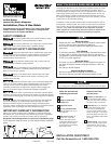
INSTALLATION INSTRUCTIONS
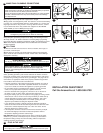
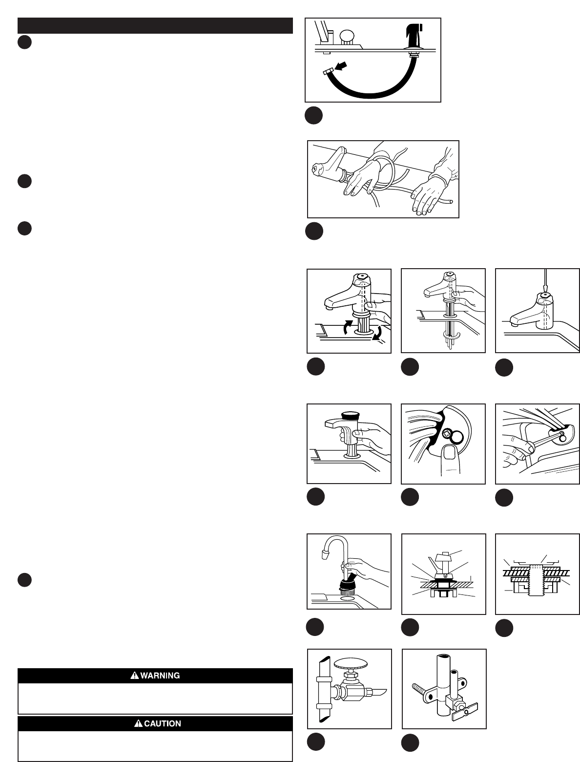
1 IF YOU WISH TO USE THE HOLE IN WHICH THE SPRAY
HOSE IS LOCATED, FOLLOW THESE EASY STEPS:
1. Turn off water supply
2. Remove nut that connects spray hose at bottom of faucet.
3. Remove nut that connects spray hose at bottom of washer flange in spray
hole using ordinary wrench or basin wrench.
4. Plug faucet tube opening with either a 1/8" plug or a 1/4" cap (not supplied)
What if you don’t use a sprayer hole?
You can cut a mounting hole through a stainless steel sink with a 1-1/4" (32mm)
chassis punch. Rent or purchase one at your hardware or electrical supply
store. Or, mount the Hot Water Dispenser’s head in a 1-1/4" (32mm) hole drilled
through your countertop with a hole saw. Don’t attempt to drill a hole through a
cast iron or porcelain covered sink unless you have the proper tools and skills.
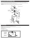
2 STRAIGHTEN DISPENSER TUBES
There are two copper tubes exiting from the dispenser head, which are curved for
easier packing and shipping. Straighten, holding the head down with one hand
while working the tubes down slowly with your other hand. See Caution, Step 9.
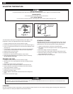
3 INSTALL DISPENSER HEAD
H-990
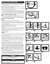
1. Place dispenser assembly (without handle) thru sink hole.
2. Place toggle on bolt from bottom, then the nut and tighten by bolt head
located on top of the faucet. Note that the open area on the toggle is positioned
around the copper lines and vent lines. Note that the toggle is mounted with
the nut holder facing down.
3. Hand tighten toggle bolt until faucet cannot easily be twisted from side to
side. Torque on bolt should not exceed 30in. Lbs.
Note: Ensure toggle bolt head is seated in recess
H-770
1. Place the dispenser head with #10-24 mounting screw and gasket attached
down through the mounting hole. Then while an assistant holds the dispenser
head in place, secure the head as shown in 3-2 and 3-3.
2. Working from below the sink, place semi-circular metal mounting washer
over the mounting screw.
3. Now, simply tighten.
GN/HC
1. Remove wing nut from valve body for 1-1/4" (32mm) sink hole, stack 1-5/8"
rubber washer, 1-5/8" stainless washer or 2-1/4" colored washer. For cast iron
sink or hole greater than 1-1/4", stack 1-5/8" rubber washer with 2-1/4" stain-
less or 2-1/4" colored washer.
2. Have someone hold the head assembly from above and, while working
from under sink, slide the 2-1/4" fiber washer into place and tighten the
assembly using the plastic wing nut.(A): Shroud (B): Set screw for adjusting
head direction (C): countertop or sink 7/8" max (22mm) (D): Wing nut (E):
2-1/4" fiber washer (F): 1-5/8" rubber washer (G): 1-5/8" stainless washer
or 2-1/4" colored washer
3. Cast iron sink hole greater than 1-1/4" (32mm) (A): 2-1/4"SS or colored
washer (B): 1-5/8" rubber washer (C): Fiber Washer (D): Wing nut
If desired, the spout may be rotated 90˚ in either direction to allow the dis-
penser levers to be on the left or right side of the spout. To do this, remove
shroud which snaps onto inner cover. Using small screwdriver, loosen set screw
on left side of valve body and rotate spout in desired direction. Do not pull
spout up or out! RETIGHTEN SET SCREW AND REPLACE SHROUD.
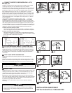
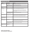
4 MAKE CONNECTION TO COLD WATER SUPPLY LINE
1. The recommended connection can be made using a shutoff valve. This is a
complex installation and should only be attempted by an experienced installer
with the proper knowledge and tools.
2. Where plumbing codes permit, a saddle valve (not supplied) can be used to
supply water to the dispenser. If the saddle valve is to be used on copper pipe
it is not necessary to pre-drill any holes. Simply follow the directions for “self-
piercing attachments” included with the valve. (Attach the valve to a cold water
supply line) Note: Saddle valves are susceptible to clogging.
Product Damage
Excessive use of paste or tape pipe sealants on water connections can
clog small water passages.
Electric Shock Hazard
Never use an electric drill to drill into water pipes. It can result in an electric
shock. Use a cordless or non-electric hand drill.
2
3
4
1
3 -1
4 -1
4 -2
3 -2
3 -3
3 -1
3 -2
3 -3
A
B
C
D
E
F
G
A
D
C
B
3 -1
3 -2
3 -3
2
MODEL H-990
MODEL H-770
MODEL GN/HC


