A
B
C
Release
Button
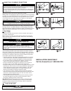
Product Damage
• Do not connect electric power until tank is filled with water (step 10).
• Failure to do so may damage heating element or trip the thermal over
load protector.
5 -1
6 -1
6 -2
7 -1
7 -2
8 -1
8 -2
8 -3
5 -2
5 -3
INSTALLATION QUESTIONS?
Call the Answerline at 1-800-558-5700
Product Damage
Do not plug unit in until tank is filled with water and water flows from spout.
A
B
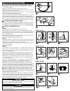
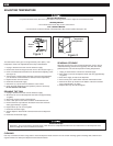
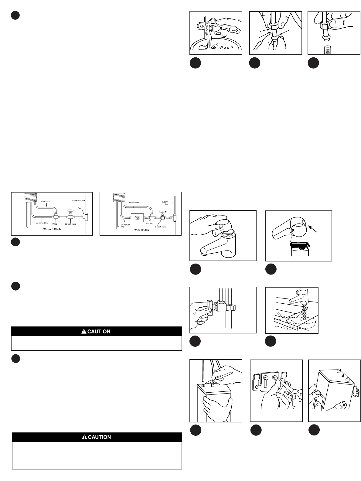
5 CONNECT WATER TO DISPENSER HEAD – H770,
H990, GN
1. Before you start open the shutoff valve and let a small amount of water
run through it into the pan. This will flush the line of any sediment.
2. When connecting to a compression type fitting (tee or valve), remove the
nut and ferrule (a rounded brass fitting) from the valve. Then place the nut
followed by the ferrule over the end of the LONGEST copper tube coming
from the dispenser head. (A): Nut (B): 1/4" copper tube (C): Ferrule
3. Push the tube end all the way into the valve opening, or tee fitting. Hold
the tube end in position and push the ferrule down as far as it will go. Now,
tighten the nut over the ferrule with your fingers. Make sure the tube end is
going straight into the hole. Then tighten the nut firmly with a 1/2" wrench.
Do not overtighten.
CONNECT WATER TO DISPENSER HEAD – H/C ONLY
The HC dispenser has two incoming 1/4" water lines. One line (color coded
white) supplies water to the tank for 190˚F(88˚C)* hot water. The other line (no
color code) supplies water from the water supply line. The two lines may be
connected through two (2) tees to a common water supply line (see diagram A)
or if a water chiller is used, the unmarked line is connected to the chiller (see
diagram B). Shown are typical installations with tees and shut-off valve.
A. Water connection without a chiller
Connect both the white coded and the unmarked 1/4" copper line, thouth a
1/4" tee to a supply line tee. Locate shutoff valve to shut off flow to dispenser.
B. Water connection with water chiller
Connect the white coded 1/4" copper line to a supply line tee.Connect the
unmarked 1/4" copper line to the water chiller outlet. Connect chiller to supply
line tee. See chiller manufacturer’s instructions.
*Approximate
6 ATTACH DISPENSER HANDLE (model H-990 only)
Place handle over top of dispenser assembly. Align hole on inside front of
handle with black peg. Use a downward and rolling movement to the back
until the handle “clicks” into place. The handle can be removed by pressing
the release button on the back of the handle and tilting the handle down
and forward.
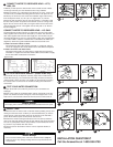
7 TEST YOUR WATER CONNECTION
1. Open the shutoff valve all the way and see if your connections are
watertight.
2. Place a pan under the unattached tubes and turn the handle on the dis-
penser. You should see water coming out of the small copper tube. Let the
water run for a few seconds to flush out the lines, then turn the faucet off.
8 MOUNT TANK
1. Mount the tank on either a back or side wall. Start by holding tank up and
making sure the tubes reach it. When you have decided where you want to
mount the tank, mark the position of the top of the tank on the wall with a
pencil. Allow sufficient space under tank for drain access.
2. Position the metal mounting bracket about one inch (25mm) below the
mark on the wall and attach it through the slots with the two screws provided.
The use of (2) #8 plastic anchors (not provided) is recommended for mount-
ing screws in any material other than wood.
3. Hang the tank on the bracket. There is room to adjust the bracket, if
necessary.


