


Page 12 15627-4-0806
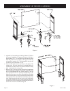
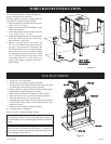
x 19 3/8" heat shield with the front of the appliance. Align the
(4) tabs with clearance holes on the 12" x 19 3/8" heat shield
with the (4) screw holes on the heat exchanger top. Attach the
12" x 19 3/8" heat shield to the heat exchanger top with (2)
1/2" hex-head screws removed in Step 5 and (2) 1/2" hex-head
screws provided in hardware package.
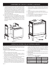
6. Place the casting top onto the casting. The casting top nests
into the casting.
7. Insert center stone inlay, left stone inlay and right stone inlay
into casting top.
8. Installation of stone inlay is completed.
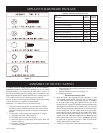
Parts List
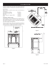
Whenever the standard grill top is replaced with a stone inlay you
must install the top shield and heat shield, which are provided
with the stone inlay.
Installation of Optional Stone Inlay
1. Remove left grill, center grill and right grill from casting
top.
2. Remove casting top from outer casting.
3. Place the casting top on a non-abrasive surface in order to
protect the porcelain finish. The exterior of the casting top
should be facing the non-abrasive surface.
4. Attach 11 5/8" x 11 5/8" top shield to the interior of the casting
top with (1) 3/8" bolt provided in hardware package.
5. Remove the (2) 1/2" hex-head screws located on the front of
the heat exchanger top. The screws are 8 3/4" apart. Do not
remove the center hex-head screw. Remove the (2) screw hole,
knockouts located on the back of the heat exchanger top. The
knockouts are 8 3/4" apart. Position the angled front on the 12"
12. The following procedure will provide a snug fit between the
casting front and the casting sides. Grasp the right, front leg,
push inward on the leg in order to provide a snug fit between
the casting front and the casting side. Continue to hold the
right, front leg as you completely tighten the (2) 3/8" bolts that
attach the leg pad to the right, casting side. Repeat procedure
for left, front leg to achieve a snug fit between the casting
front and the casting side.
13. Remove the casting front from the casting.
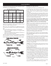
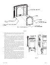
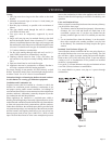
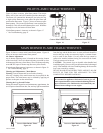
14. Refer to Figures 10 and 11, the appliance firebox can now
be inserted into the casting. Center the firebox in the casting.
Attention: Remove (1) Phillips-head screw in the top of the
valve cover. The screw is used to secure the valve cover in
place during shipping. The (1) Phillips-head screw can be
discarded.
Figure 10 Figure 11
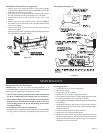
15. Refer to Figure 12, align (4) clearance holes on rear cover
with screw holes in (2) upper mounting brackets and diverter
back assembly. Attach firebox to rear cover with (4) 10 x 1/2"
screws.
16. Attach casting front to casting as described in Step 11.
17. Place the casting top onto the casting. The casting top nests
into the casting.
18. Insert center grill, left grill and right grill into casting top.
19. Level appliance by adjusting leveling bolts.
20. Assembly of stove casting is completed.
ASSEMBLY OF STOVE CASTING (continued)
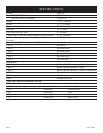
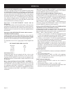
OPTIONAL STONE INLAY INSTALLATION
Part Description Part Number Quantity Supplied
11 5/8" x 11 5/8" Top Shield
CI-091 1
12" x 19 3/8" Heat Shield CI-092 1
3/8" Bolt R-3646 1
1/2" Hex-Head Screw R-2737 4