


Page 1315627-4-0806
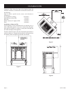
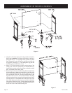
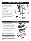
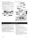
WIRE CHANNEL INSTALLATION
The ON/OFF/REMOTE switch with harness is
factory installed into the switch box.
After the appliance housing is installed into the
casting the wire channel can be installed.
1. Attach switch box on the left side of rear cover
with (2) 10 x 1/2" screws.
2. Route wires from ON/OFF/REMOTE switch
within wire channel.
3. Attach wire channel on the left side of the rear
cover with (4) 10 x 1/2" screws.
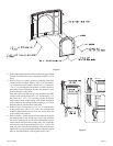
4. Attach the black and green (wires) female push-
ons to the TH/TP and TH (two outside male
tabs) terminals on gas valve.
5. Identify vent safety switch wire harness. The
first wire is installed into magnet section on
gas valve. The second wire is attached to the
TH/TP terminal on gas valve. Route opposite
end of vent safety switch wire harness within
(2) metal clips on exterior of rear cover. Attach
(2) 1/4" female push-ons on vent safety switch
wire harness onto (2) 1/4" male tabs on vent
safety switch which is located on the side of
draft diverter.
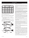
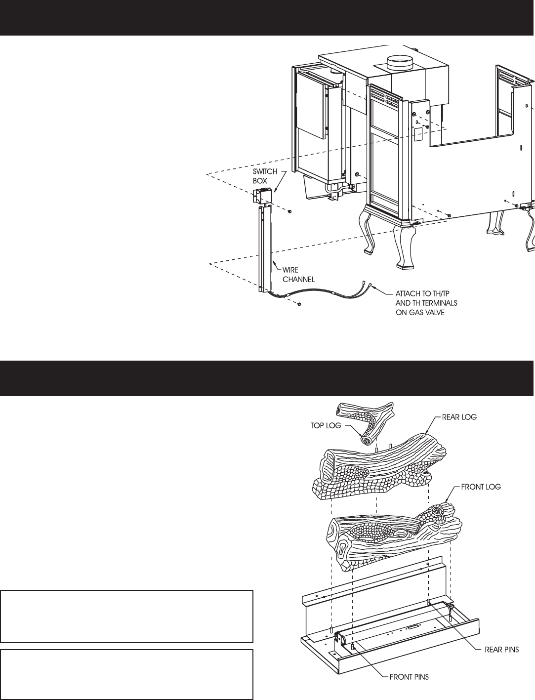
Figure 12
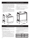
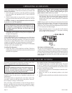
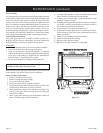
Figure 13
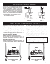
1. Lower valve cover on firebox.
2. Release two door latches at bottom of firebox.
3. Grasp bottom of glass frame, lift glass frame upward in order
to release glass frame from lip on top of firebox.
4. Remove logs from interior of firebox. Remove all protective
packaging from logs and interior of firebox.
5. Place front log onto two (2) front pins on inner bottom.
6. Place rear log onto two (2) rear pins on rear log support.
7. Place top log onto two (2) pins on rear log.
8. Align and place top of glass frame over lip on top of firebox.
Grasp bottom of glass frame, push inward and place glass
frame onto firebox.
9. Attach two door latches to bottom of firebox.
10. Log placement is completed.
Refer to Figure 13 for the following warning.
Warning: Failure to position the parts in accordance with
this diagram or failure to use only parts specifically approved
with this appliance may result in property damage or personal
injury.
Avertissement: Risque de dommages ou de blessures si les
pièces ne sont pas installées conformément à ce schéma et
ou si de pièces autres que celles spécifiquement approuvées
avec cet appareil sont utilisées.
LOG PLACEMENT