


Version 02/02 - Page 5
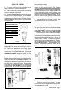
4. Determine and make necessary cuts for the ductwork.
The duct opening is shown on the mounting template (Item E
in Figure 5). Install ductwork before mounting the support.
5. Determine the proper location for the Power Supply
Cable as indicated on the template. Use a 1 1/4" Drill Bit to
make this hole. Run the Power Supply Cable. Use caulking
to seal around the hole. DO NOT turn on the power until
installation is complete! A knockout is provided near the
exhaust exit on the canopy for the Power Supply Cable.
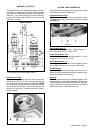
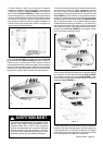
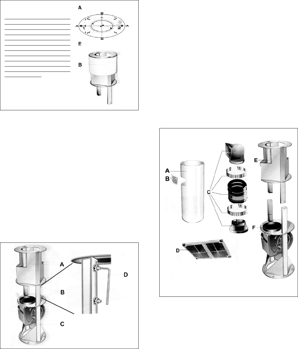
6. Attach the Upper Support to the ceiling (Item A in
Figure 6). Make sure that the support is firmly attached to the
ceiling. Install the Lower Support (Item C in Figure 6). The
canopy height over the range is determined by the length of
the support. The bottom of the canopy will be approximately 2
5/8 inches below the bottom of the support. Once the length
of the support is determined, tighten the four screws using
an Allen Wrench (Item D in Figure 6) to secure the Lower
Support in place. All four screws must be firmly tightened
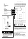
ATTACH THE SUPPORT
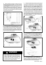
1. Put a thick, protective covering over cooktop, set-in
range or countertop to protect from damage or dirt.
2. Determine and clearly mark with a pencil on the ceiling
where the rangehood will be installed.
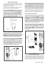
3. A template (Item A in Figure 5) for mounting the support
is supplied in the carton with the support. Use this template
to mark holes for support on the ceiling. The chimney must
be disassembled to reveal the support. The Upper Chimney
(Item B in Figure 5) is held in place by two screws which
must be removed.
FIGURE 6
FIGURE 5
before attaching the canopy.
7. Remove the cover from the field wiring compartment.
Remove the wiring electrical knockout using a flat-blade
screwdriver. DO NOT turn on the power until installation is
complete! Connect the Power Supply Cable to the rangehood.
Attach the White lead of the power supply to the White lead
of the rangehood with a twist-on type wire connector. Attach
the Black lead of the power supply to the Black lead of the
rangehood with a twist-on type wire connector. Connect
the Green (Green and Yellow) ground wire under the Green
grounding screw.
8. Attach the duct work to the top of the blower. Make
sure to seal all joints with duct tape to prevent leaks.
For ductless installations:
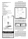
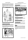
Ductless installations require a ductless kit. This kit consists of
one upper chimney cover with a hole for the exhaust air (Item
A in Figure 7), a vent grid to cover the hole in the chimney
cover (Item B in Figure 7), a ductless diverter assembly (Item
C in Figure 7), and two charcoal filters (Item D in Figure
7). The ductless diverter must be installedbefore the upper
chimney cover. The chimney cover without a vent hole will
not be needed for this installation and should be discarded.
Before installing the upper chimney cover, the vent grid
assembly must be installed. The bottom of this assembly
must attach to the blower (Item F in Figure 7). The upper
end must be positioned at the opening in the upper chimney
support (Item E in Figure 7). Install the ductless diverter
assembly. The charcoal filters will be installed after the
rangehood is completely installed.
FIGURE 7
INSTALL THE CANOPY
1. Remove the grease filters and set aside. The grease
filters are removed by pressing the handle in front of the filter.
When replacing, make sure the filters are properly positioned
with the handles visible in front.
IMPORTANT NOTE: BE CAREFUL
WHEN DETERMINING THE
LOCATION FOR THE HOLE IN
YOUR CEILING FOR THE DUCT
WORK. THIS HOLE SHOULD
NOT BE CENTERED OVER THE
CENTER OF THE COOKING
SURFACE AS THE DUCT WORK
THAT RUNS UP INSIDE THE
CHIMNEY AND THROUGH THE
CEILING IS NOT IN THE CENTER
OF THE CHIMNEY.