


Version 5/07 - Page 4
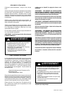
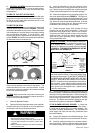
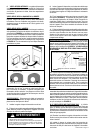
9 Feet Straight Duct
2 - 90˚ Elbows
Wall Cap
Total System
9.0 feet
14.0 feet
0.0 feet
23.0 feet
FIGURE 4
5.0 feet
7.0 feet
12.0 feet
0.0 feet
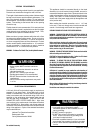
45˚ Elbow
90˚ Elbow
90˚ Flat Elbow
Wall Cap
FIGURE 3
FIGURE 2
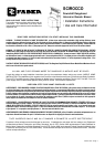
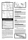
REMOTE BLOWER DUCTING
FIGURE 1
VENTING DOWN VENTING LEFT
VENTING RIGHT VENTING BACK
INTERNAL BLOWER DUCTING
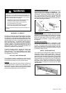
TOOLS NEEDED FOR INSTALLATION
• Saber Saw or Jig Saw
• Drill
• 1 1/4" Wood Drill Bit
• Pliers
• Phillips Screwdriver
• Flat Blade Screwdriver
• Wire Stripper or Utility Knife
• Metal Snips
• Measuring Tape or Ruler
• Level
• Pencil
• Caulking Gun
• Duct Tape
PARTS SUPPLIED FOR INSTALLATION
• 6 Mounting Brackets
• 2 End Caps
• 16 Screws
• 1 Literature Package
• 1 Backdraft Damper - Internal Blower Model Only
PARTS NEEDED FOR INSTALLATION
• 2 Conduit Connectors
• Power Supply Cable
• Wiring Cable - Optional Remote Blower Only
• 1 Wall or Roof Cap
• All Metal Ductwork
OPTIONAL ACCESSORIES AVAILABLE
• Remote Blower
for remote blower downdrafts only, model# 630001732
• Trim Kits
to replace the stainless steel top trim with a black or white trim
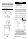
PLAN THE DUCTWORK
The Scirocco downdraft system is designed to offer wide flex-
ibility in ducting. The interior blower can be ducted in four
different directions; down, left, right or back using a 3 1/4"
X 10" rectangular vent. The remote blower can be ducted
in three directions; down, left or right using a 10" round vent.
FIGURES 1 and 2 illustrate venting options.
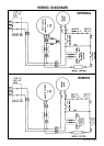
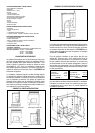
The remote blower requires a separate wiring cable that should
be installed at the same time that the ductwork is installed. For
best results, 10" duct is recommended for the remote blower.
A damper plate is included in the box with the remote blower
and must be attached over the opening of the front of the
downdraft blower box. Remote blower can be mounted on
either an outside wall or the roof of the home.
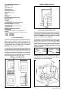
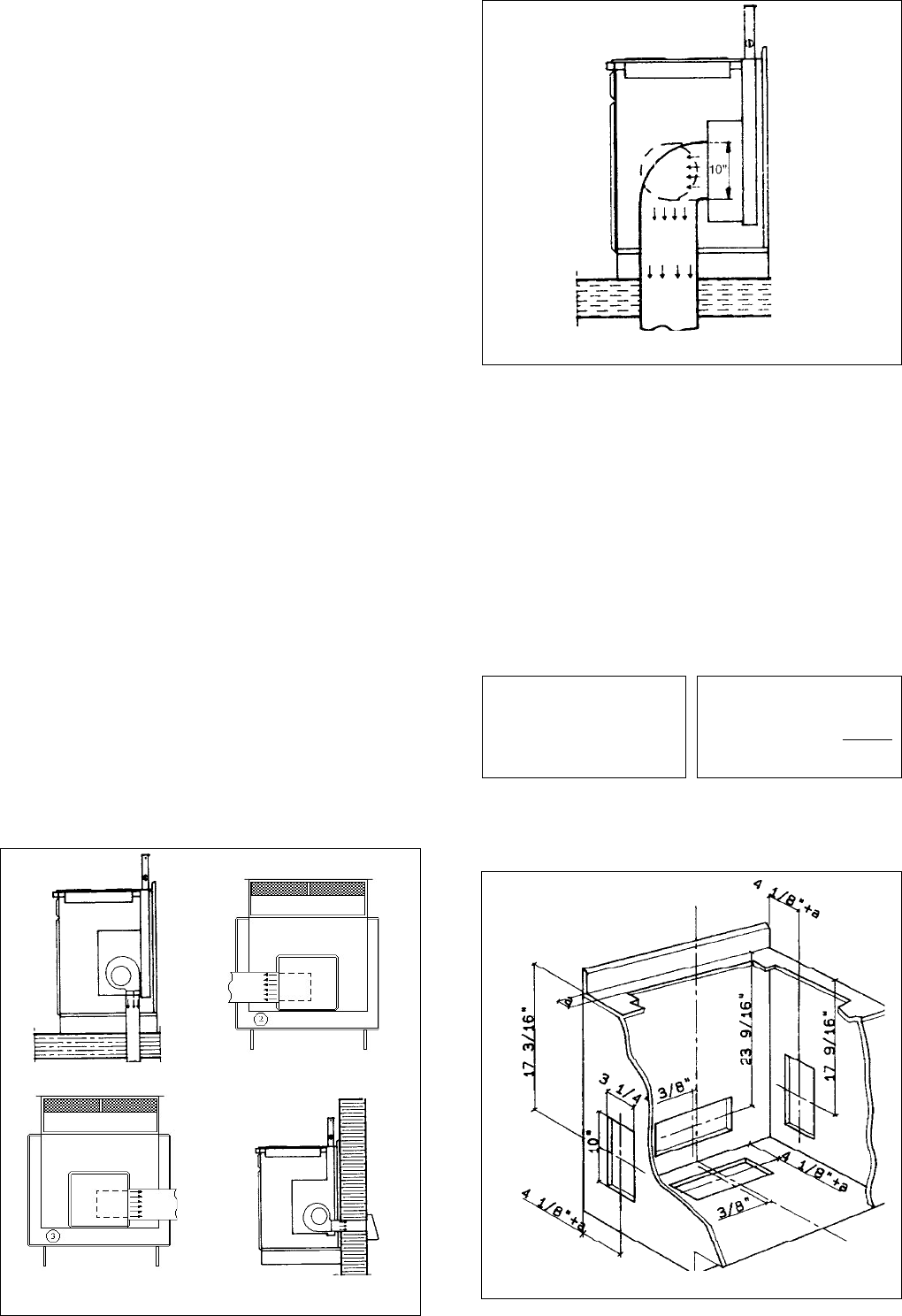
FIGURE 5 shows the ductwork cutout dimensions for the
internal blower model only. The remote blower connects us-
ing a 10" round duct. The location of the cutout for this duct
will depend upon your specific installation.
FIGURE 5
CALCULATE THE DUCTRUN LENGTH
The ductwork length should not exceed 35 equivalent feet for 3
1/4" X 10" duct, or 55 equivalent feet for 9" or 10" round duct.
Calculate the length of the ductwork by adding the equivalent
feet listed in FIGURE 3 for each piece of duct in the complete
system. An example is given in FIGURE 4.
For best results, use no more than three 90° elbows. Make
sure that there is a minimum of 24" of straight duct between
elbows if more than one is used. Do not install two elbows
together. Round duct is recommended instead of rectangular
duct especially if elbows are needed. For internal blower
models, rectangular duct should be transitioned to 6" round
as soon as possible.
30 White part# 6096090
36 White part# 6096091
30 Black part# 6096092
36 Black part# 6096093