


Version 5/07 - Page 6
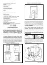
6. INTERNAL BLOWERS Internal blower downdrafts are
shipped from the factory ready to vent in the down position.
If you need to vent back, left or right, then the blower must
be repositioned.
TO VENT TO THE LEFT OR THE RIGHT
Four hex nuts attach the blower box to the downdraft body.
Remove all four nuts and carefully remove the blower box.
To vent left or right, simply rotate the blower box 90° to the
left or right and re-assemble.
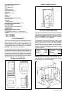
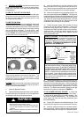
TO VENT TO THE REAR
Venting to the rear requires that the blower be repositioned
inside the blower box as indicated in FIGURE 9. The blower
is attached to the blower box by 6 screws. Remove the blower
from the blower box. Note the position of the angle mounting
rails on each side of the blower. To vent to the rear, both
mounting rails must be repositioned on the blower as illus-
trated in FIGURE 10. Attach the mounting rails as indicated.
Re-attach the blower to the blower box.
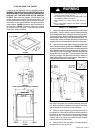
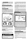
When attaching the Under Counter Mounting Brackets:
• DO NOT drill into the countertop surface.
• Check that the mounting screws are proper length and
will not extend through the countertop surface when
tightened.
Failure to follow these warnings could result in damage to
the countertop surface.
FIGURE 9
FIGURE 11
FIGURE 10
Re-attach the blower box to the downdraft. The square metal
frame must be attached to the mouth of the blower. The
exhaust knockout on the rear must be removed. A metal
plate and two screws are supplied in the hardware package
to cover the unused exhaust exit.
CAUTION: Make sure that the wiring cable connecting the
blower to the field wiring compartment remains securely at-
tached under the two cable clamps.
7. Attach the Backdraft Damper.
8. Remove the field wiring compartment cover and deter-
mine which direction the wiring will run from the appliance to
the wiring box and remove the wiring knockout.
9. Insert the downdraft unit into the countertop cutout.
Make sure that the unit is firmly placed at the rear of the cut-
out. Fasten the legs to the cabinet floor using the two longer
Phillips head screws supplied in the hardware package.
10. Attach the downdraft to the countertop using the Un-
dercounter Mounting Brackets (FIGURE 8). This system is
designed to adjust to different countertop thicknesses. Using
the small Phillips head machine screws in the hardware pack-
age, attach one Undercounter Mounting Bracket to the slot
on the upper right corner of the unit. Attach the other end of
the Bracket to the underside of the countertop.
11. Thread the power supply cable through the wiring
knockout into the field wiring compartment. Connect the
three White wires together with a twist-on wire connector.
Connect the two Black wires with a twist-on wire connector.
Attach the Green ( or Green and Yellow) ground wire to the
eyelet with the green grounding screw. Replace the field
wiring compartment cover.
Venting Left, Right or Down
Venting to the Rear
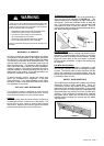
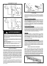
REMOTE BLOWERS The remote blower must be con-
nected to the downdraft by a separate wiring cable which
is not supplied with the downdraft. A separate wiring
knockout is supplied for the remote blower as indicated
in FIGURE 11. THE REMOTE BLOWER MUST NOT BE
WIRED INTO THE WIRING BOX.
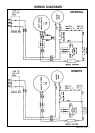
WIRING
KNOCKOUT
FOR
CONNECTING
THE REMOTE
BLOWER
WIRING BOX
FOR POWER
SUPPLY
TO THE
DOWNDRAFT.
DO NOT WIRE
THE REMOTE
BLOWER
CABLE INTO
THIS WIRING
BOX.
12. Remove the wiring knockout for the remote blower
and install conduit connector. Feed remote blower wiring
through conduit connector. DO NOT WIRE THE REMOTE
BLOWER BLACK AND WHITE WIRES INTO THE WIR-
ING BOX. WIRES MUST BE CONNECTED AS SHOWN
ABOVE. Connect the white wires together with a twist-on
wire connector. Connect the black wires together with a
twist-on wire connector. Attach ground wire to eyelet with
green ground screw and tighten screw. Tighten conduit
connector clamp screws.
WARNING
!
13. Turn the power supply on. Push and hold the Up/Down
button momentarily. The downdraft will rise out of the countertop
and stop in the fully extended position. Position the top strip
over the the top of the downdraft, lining up the fixing hooks
and the hole for the push button. Snap into place. Turn the
blower on. The blower control switch is located on the right
hand side of the plenum as indicated in FIGURE 12.
IF THE BLOWER DOES NOT OPERATE: (1) Check that
the circuit breaker is not tripped or the house fuse blown. (
2) Check that the grease filters are properly installed. ( See
the section on Safety Microswitches ), (3) Disconnect the
power supply and check that the wiring connections have
been made properly.
14. Connect the ductwork to the Backdraft damper. Seal
all joints with duct tape and vent to the outside of the home.
15. Install the cooktop according to the cooktop manufac-
turer's instructions. Check to make sure that the rear edge of
the cooktop overlaps the front edge of the downdraft by 3/8".