


Version 5/07 - Page 5
PLAN AND MAKE THE CUTOUT
A template for the downdraft cutout is supplied in the box.
WARNING: THIS TEMPLATE ILLUSTRATES THE CUTOUT
IN RELATIONSHIP TO THE REAR EDGE OF THE COOKTOP
SURFACE, NOT THE REAR EDGE OF THE COOKTOP
CUTOUT! When using this template, the rear edge of the
cooktop must be determined before marking this cutout. It is
recommended that the Installer draw the cooktop and down-
draft cutouts on the countertop before making any cutouts to
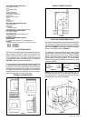
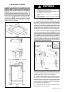
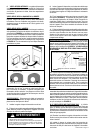
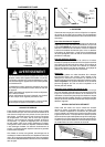
avoid mistakes. FIGURE 6 shows the cutout dimensions for
the downdraft. FIGURE 7 shows the tolerances between
the cooktop and the downdraft. These tolerances must be
observed for proper installation.
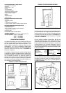
FIGURE 7
WARNING!
THESE TOLERANCES MUST BE OBSERVED!
FIGURE 6
When planning the cutout for the downdraft:
• Draw both the cooktop and downdraft cutouts on the
countertop before making any cuts.
• The rear edge of the cooktop must be determined to use
the template included in the carton.
• Check that there is enough room in the cabinet for
both.
Failure to follow these warnings could result in damage
to the countertop.
INSTALL THE DOWNDRAFT
1. Remove the unit from the carton and place on a flat surface
for assembly. Cover the surface to prevent accidental damage.
Remove all downdraft parts including the 6 mounting brackets, 2
end caps, 16 screws, literature package, and backdraft damper
(Internal Blower Model Only) before discarding the carton. For
remote blower models, the damper plate that is included with the
remote blower must be attached to the front of the blower box.
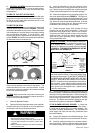
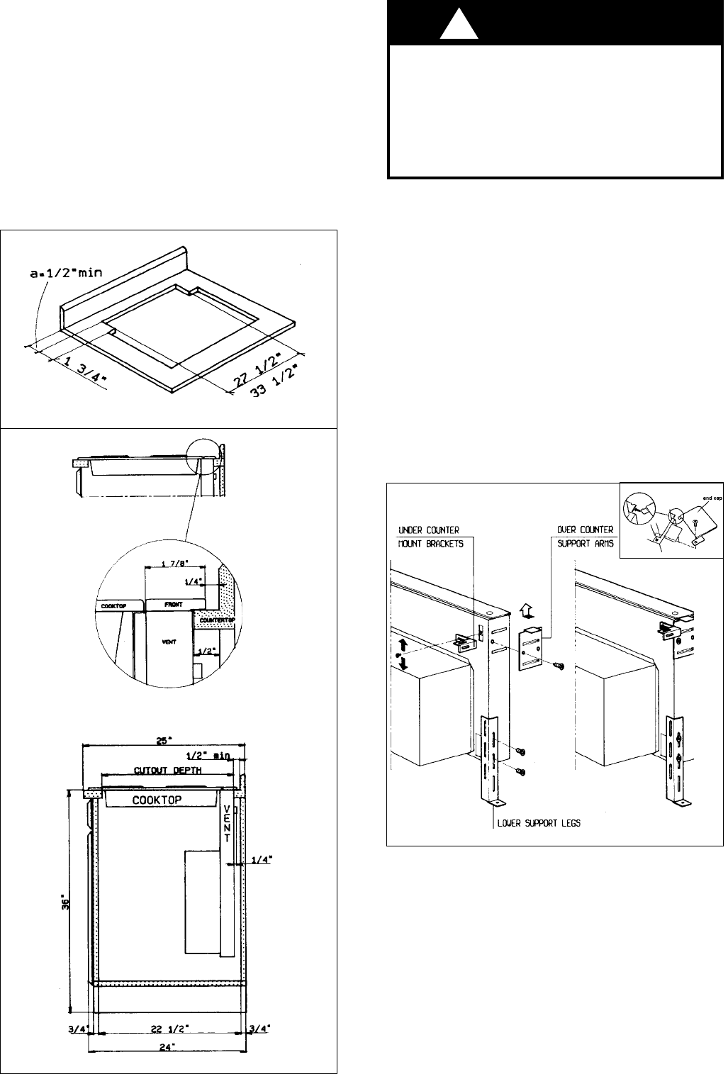
2. Attach the Overcounter Support Arms to the left and right
sides of the downdraft body as indicated in FIGURE 8. Two short
screws are provided. Attach the end caps to the left and right sides
of the downdraft over the Overcounter Support Arms. Attach the
Lower Support Legs to left and right sides of the downdraft into
the threaded slots on each side. The Lower Support Legs have
holes for mounting to the cabinet floor and can be installed on
either side depending upon the length required. Determine if the
holes should be in the front or on the sides.
FIGURE 8
3. Carefully insert the unit into the cutout. Due to the size
and weight, two people are recommended when lifting this
unit. Make sure that the downdraft is fully seated in the cutout
and the support arms rest firmly on the countertop.
4. Adjust the Lower Support Legs until both rest firmly on
the cabinet floor. Place a level vertically on the front side of the
blower box to make sure that the unit is level and not leaning
to the front or rear. Once the unit is properly aligned, mark
a starter hole on the cabinet floor where the Lower Support
Legs will attach to the cabinet floor.
5. Remove the unit from the cabinet. Drill starter holes in
the cabinet floor for the leg screws.
WARNING
!