


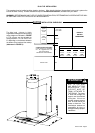

Version 3/08 - Page 8
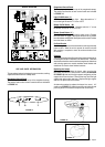
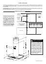
For ductless installations, install the CHARCOAL FILTER (G in
FIGURE 8)
and locking into place.
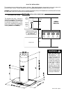
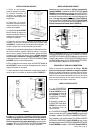
WARNING
-
HOOD, THREE PEOPLE ARE REQUIRED TO
INSTALL THE CANOPY. Two people must hold the
canopy in place while the third person installs the
screws that attach the canopy to the chimney. The
manufacturer assumes no responsibility for injury or
damage caused by improper installations.
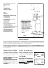
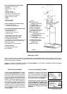
4. From below, attach the CANOPY SECTION (A in FIGURE
10) to the assembled chimney support using the four screws
provided (F in FIGURE 10).
FIGURE 10
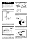
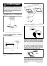
FIGURE 13
FIGURE 12
7.
turning the knob to the left so that the locking lever does not
(as in FIGURE 14). Insert the opposite
FIGURE 14
8. Turn the power supply on. Turn on blower and lights. If the
rangehood does not operate, check that the circuit breaker is
not tripped or the house fuse blown. If the unit still does not
operate, disconnect the power supply and check that the wiring
connections have been made properly.
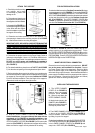
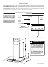
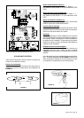
6. Run the control cable (A in FIGURE 12) from inside the
chimney through the hole (H in FIGURE 11) in the appropriate
bracket. Be sure to place the black rubber grommet around
the cable inside the hole to protect the cable from being nicked
by the metal hole. Connect the control cables together as
indicated in FIGURE 12. Tuck them away under the brackets
and reinstall the brackets. Repeat this process for the lighting
cables (B in FIGURE 12).
FIGURE 11
5. Remove the metal brackets located on the top and bottom of
the underside of the rangehood by removing the screws (FIGURE
11). Removing these brackets provides access to the control
and lighting cables which must connect to the control and lighting
cables from the inside of the chimney (FIGURE 12).
H
MAKE THE INTERNAL ELECTRICAL CONNECTIONS
B
A
!