


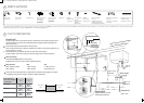
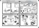
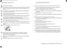
PARTS SUPPLIED
Clamp (1)
Wire clip (1)
Phillips
⁄” (16 mm)
screws (7)
1
½ ” (38 mm)
bottom
fixing screws
& metal
washers (2)
Drain hose
support (1)
Moisture protection
tape (1)
(to prevent moisture
damage)
Cavity bracket
kit (1)
(supplied only with
Prefinished flat door
and Integrated models)
Drain hose
joiner (1)
Rubber
washer for
inlet hose (1)
Edge protector (1)
(if services hole
partition is metal)
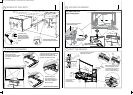
If the Drain hose(s) supplied are not long enough to reach your services, you must use a Drain Hose Extension Kit P/N 525798 which will extend the drain hose(s) by 11’ 10” (3.6m). The kit is available from the nearest Fisher & Paykel
Authorized Service Agent, or Toll free 1.888.936.7872 or www.fisherpaykel.com.
4
5
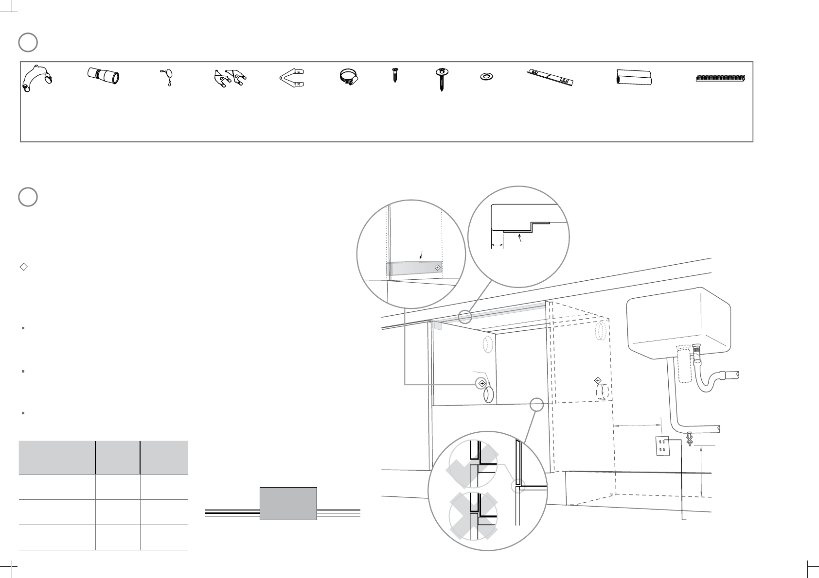
Important!
Be sure the edges of the services hole are smooth or covered. If the services hole is through a metal
partition the hole must be protected with the Edge protector supplied to prevent damage to the
power cord or hoses.
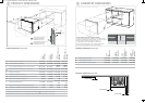
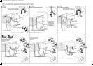
These marks indicate formed bracket screw locations.
Note: To align drawer front to adjacent cabinetry, the product to countertop clearance can
be increased to
⁄” (
3 mm).
Preferred position. If adequate clearance, services hole can be higher.
If hole is higher, ensure drain hose(s) are routed straight into the waste connection.
Water Connection
Recommended HOT (Maximum 140°F/60°C).
Supplied hose to suit 3/8” (9 mm) male compression fitting.
*
CAVITY PREPARATION
Water Pressure Max Min
Water softener models 1 MPa (145 psi) 0.1 MPa (14.5 psi)
Other models 1 MPa (145 psi) 0.03 MPa (4.3 psi)
Drains will need to be separated to satisfy kosher requirements. We suggest you confirm
acceptability with your local rabbi in respect to kosher installations.
2” x 4”
Note: Services can be located
either side of DishDrawer®.
Important!
Adjacent cabinetry must not
extend above cavity base
110-120 VAC
max. 15 A
min.
7 ⁄”
(
200 mm)
⁄”
(
10 mm)
max.
17 ⁄”
(
450 mm)
Water supply
max. ø
1 ½ ” (
38 mm)
Moisture
protection
tape must
be applied.
If no side partition,
use a brace for
securing.
*
*
Left hand
side
Right hand
side
Side mounting
bracket kit
(A and B) (2)
OPTIONAL
Top mounting
brackets (2)
OPTIONAL
Max. distance of
hoses and cord from
chassis edge
Left hand
side
Right hand
side
Drain hose
78 ½ ”
(2000 mm)
70 ½ ”
(1800 mm)
Inlet hose
64 ¾ ”
(1650 mm)
49”
(1250 mm)
Power cord (excl. plug)
29 ½ ”
(750 mm)
27 ½ ”
(700 mm)
(2,1) -1- 599754C DD24S TALL installA2 USCA.indd 15/4/09 2:34:15 PM
(2,1) -1- 599754C DD24S TALL installA2 USCA.indd 15/4/09 2:34:15 PM