


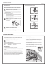

WIRING INSTRUCTIONS
1. Remove the top panel from the product.
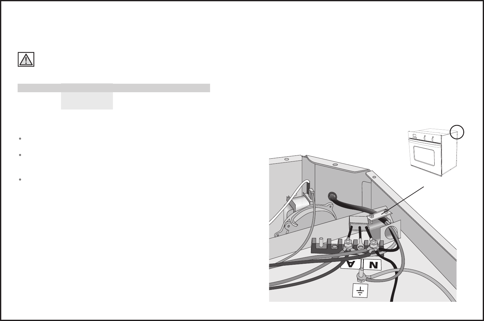
2. Feed the oven electrical supply cable through the grommeted hole on the
45
o
corner at the rear of the product. Then thread that cable through the
burst hole and the wiring clamp.
3. Connect the electrical supply cable to the earth post and mains terminal
block as indicated on the diagram below.
It is recommended to use an appropriate terminal lug to connect the cable to
the mains terminal block and earth post.
4. Secure the wiring clamp and re-fit the top panel.
PAGE 5 OF 8
PAGE 6 OF 8
ELECTRICAL REQUIREMENTS
The electrical voltage and frequency that is correct for this oven is stated on the serial
number plate located inside the top vent. It is the customer responsibility to ensure that
this oven is connected to the correct electrical supply.
WARNING : The oven must be connected to a permanent and
grounded supply.
Maximum current draw and Maximum Load:
240V 220V
Double : 38.2 A 9.2 kW 35 A 7.7 kW
Single : 21 A 5.1 kW 19.5 A 4.3 kW
WIRING REQUIREMENTS
A circuit breaker appropriate for the product is recommended.
The electrical supply conduit must be securely clamped in the cable clamp located inside
the product.
Do ensure a suitable disconnection switch is incorporated in the permanent wiring,
positioned to comply with the local wiring rules and regulations. A means of disconnection
with at least a 3mm air gap contact separation in all poles must be incorporated into the
fixed wiring in accordance with the wiring rules, unless the local wiring rules allow for the
following variation. A means of disconnection from the supply having an air gap separation
in all active (phase) conductors must be incorporated in to the fixed wiring.
PREPARING THE OVEN
UNPACKING THE OVEN
Do not use door handles or any part of the control panel for lifting the product.
Before the product is lifted, the oven doors and racks are to be removed.
WARNING : Extreme care is to be taken when lifting the product as it
is very heavy. Failure to do so may result in injury.
1. Carefully lay the product on its back. Remove the external wrapping and the
bottom polystyrene protector and pallet. Stand the product up and remove all
other polystyrene packaging.
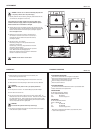
2. Remove the oven doors. This is done by:
Open the oven door fully.
Lift the catches on both of the hinges over towards you onto the hooks
of the hinge arm (see picture below).
Raise the door slightly, holding on either side near the handle, making
sure that the clips stay on the hooks.
WARNING : Do not lift the door out by the handle as this may cause
damage to the product.
Lift the door out.
WARNING : Do not disengage the hinge hooks when the door has
been removed as they are differcult to re-engage.
3. Remove the wire shelves and oven trays by sliding them out. Use both hands
to remove each item. Remove the cardboard packaging from the oven cavity.
Door Hinge
Door
Clip
Hook
wiring clamp
c
20 mm
2.5 mm
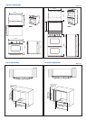
DRAWER FRONT
b
20 mm
2.5 mm
CUPBOARD FRONT
FLUSH FITTING INSTALLATION OPTIONS
a
20 mm
2.5 mm