


18
18
2
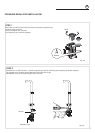
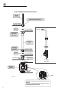
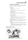
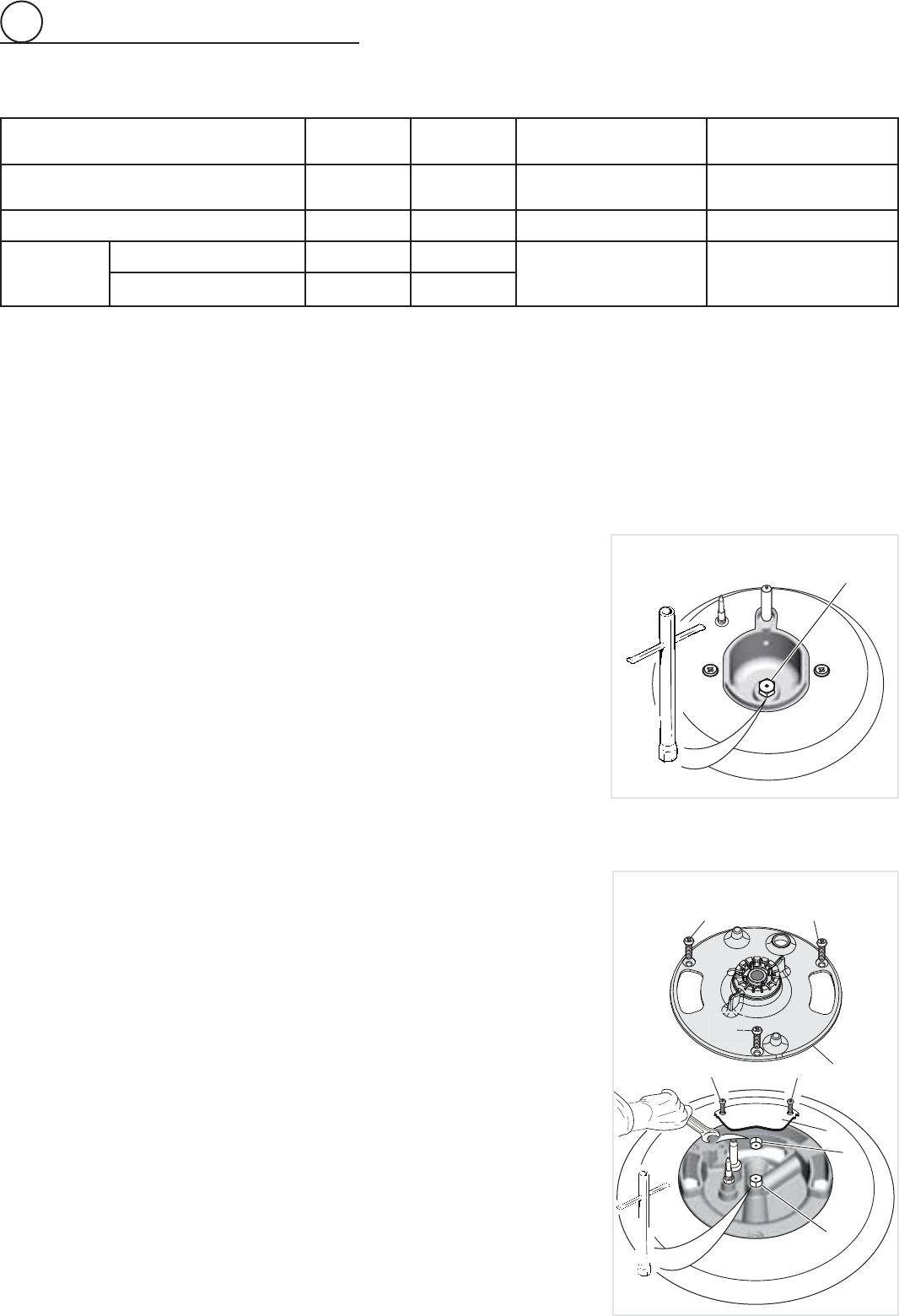
OPERATIONS TO BE PERFORMED WHEN SUBSTITUTING THE
ORIFICES
• Remove the pan supports, the burner caps and the fl ame spreaders.
• Dual burner only (fi g. 2.12): Unscrew the no.3 fi xing screws “A” and remove the inner
crown fl ame spreader “B”; then unscrew the no.2 fi xing screws “C” and remove the
cover plate “D”.
• Using a wrench substitute the nozzle orifi ces “J
1
”, “J
2
” and “J
3
” (fi gs. 2.11, 2.12) with
those most suitable for the kind of gas for which it is to be used.
• Dual burner only (fi g. 2.12):
Refi t
the cover plate “D” and screw the no.2 fi xing screws
“C”; then refi t the inner crown fl ame spreader “B” and screw the no.3 fi xing screws “A”
• Refi t the fl ame spreaders, the burner caps and the pan supports.
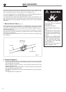
The burner are conceived in such a way so as not to require the regulation of the
primary air.
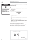
SECOND ORIFICE
DEUXIEME ORIFICE
A
A
A
B
C
C
D
J
2
J
3
Fig. 2.12
J
1
Fig. 2.11
SEMI-RAPID BURNER
DUAL BURNER
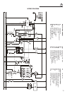
ORIFICES TABLE
NOMINAL
POWER
REDUCED
POWER
LP/PROPANE
11” W.C.P.
NATURAL GAS
4” W.C.P.
BURNERS BTU/hr BTU/hr
Ø orifi ce
[1/100 mm]
Ø orifi ce
[1/100 mm]
Semirapid (SR) 8000 1500 85 139
Dual (D)
Inner crown 2100 1000
42 (*)
115 (#)
70 (*)
200 (#)
Inner & outer crown 17000 6500
(*) inner crown (“J
2
” in fi gure 2.12)
(#) outer crown (“J
3
” in fi gure 2.12)