


19
19
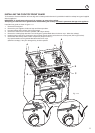
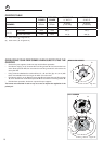
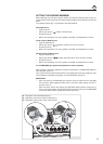
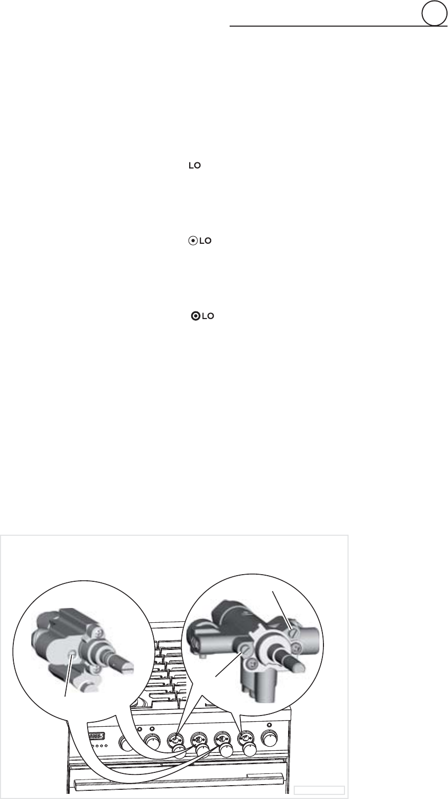
Fig. 2.13
R
1
Regulation screw (Semirapid burner)
R
2
Regulation screw (Inner crown of dual burner)
R
3
Regulation screw (Outer crown of dual burner)
R
1
R
3
R
2
2
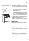
SETTING THE BURNER MINIMUM
When switching from one type of gas to another, the minimum fl ow rate must also be cor-
rect: the fl ame should not go out even when passing suddenly from maximum to minimum
fl ame.
To regulate the fl ame (fi g. 2.13) follow the instructions below:
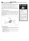
Semirapid burner
• Light the burner.
• Set the gas valve to
position (minimum rate).
• Remove the knob.
• With a thin screwdriver, turn the regulation screw “R
1
” until adjustment is correct.
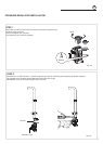
Inside crown of DUAL burner
• Light the DUAL burner.
• Set the gas valve to
position (minimum rate of inner crown).
• Remove the knob
• With a thin screwdriver, turn the regulation screw “R
2
” until adjustment is correct.
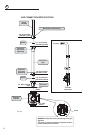
Outside crown of DUAL burner
• Light the DUAL burner.
• Set the gas valve to
position (minimum rate of inner and outer crowns).
• Remove the knob.
• With a thin screwdriver, turn the regulation screw “R
3
” until adjustment is correct.
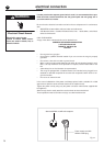
For LP/PROPANE gas, tighten the adjustment screws completely.
After regulation repeat the operations indicated in paragraph “2. PRESSURE REGULA-
TOR” at page 12 and 15.
If the range has been disconnected and then connected again to the gas supply line repe-
at the operations indicated in paragraph “5. LEAK TESTING” at page 15.
IMPORTANT:
• After conversion to LP/PROPANE gas has been carried out affi x near the data plate
the conversion label supplied and also affi x a conversion label at page 3 of this in-
struction manual.
• After conversion back to the original gas (NATURAL GAS) has been carried out re-
move, near the data plate and at page 3 of this instruction manual, the LP/PROPANE
conversion labels. Save the labels removed for future use.