


EN
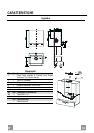
6
6
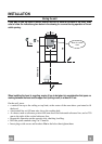
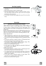
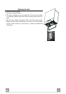
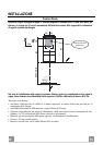
Hood body assembly
• Adjust the two screws Vr of brackets 11a, by just placing them
in position.
• Hook the hood body to the two brackets 11a.
• Pull the Comfort Panel to open it, remove the filters one by
one, push them towards the rear part of the unit and pull
downwards at the same time .
• From inside the hood body, tighten the screws Vr to level the
body.
Vr
11a
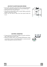
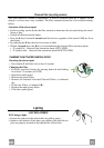
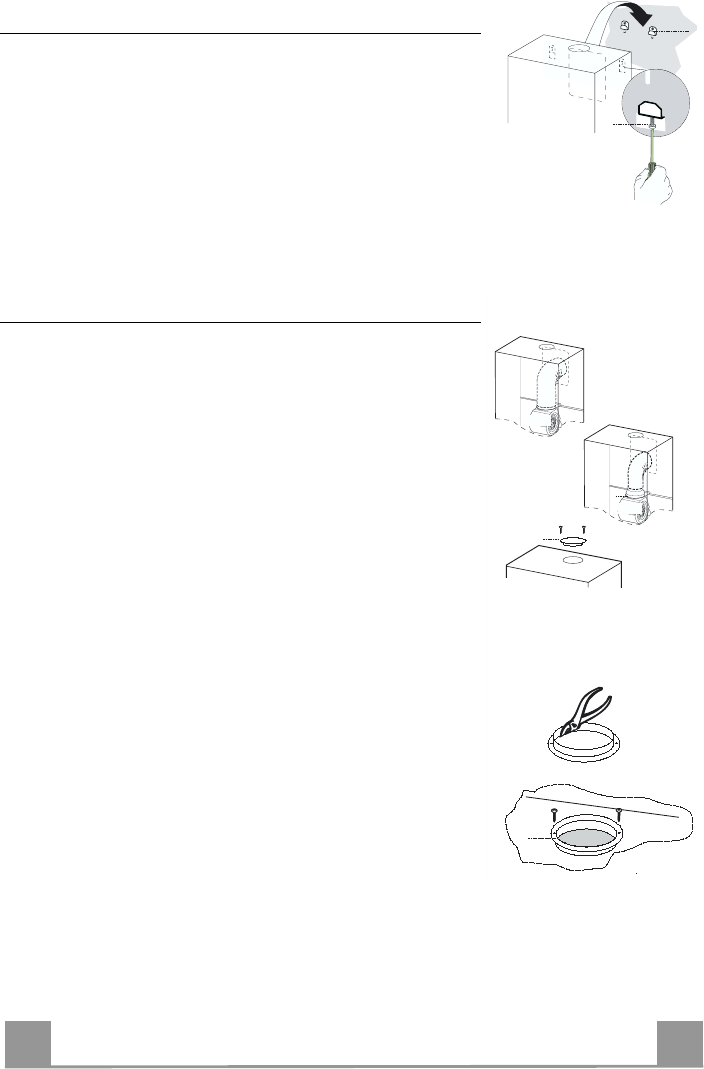
Connection
AIR OUTLET IN A DUCTING HOOD VERSION
When installing the hood in ducting version, basing on the in-
staller’s choice, a rigid or a flexible pipe with a ø 150 or 120 mm
is used in order to connect the hood to the air outlet piping. The
pipe connection can be made on the upper part or on the rear side
of the hood.
Before connecting the hood to the air outlet ducting remove the
lateral air outlet grid 8 and the plastic tube 7. The adapting flange
9 has to be removed only in case the connecting diameter is 150.
REAR AIR OUTLET
• When drilling the air outlet hole in the wall proceed in accor-
dance with the scheme in the part concerning the wall drilling.
• Use a pair of tongs when breaking the rear air outlet hole in the
wall.
• In case the connection is made by using a ø 120 mm pipe insert
the reduction flange 9 on the hood body outlet.
• Fix the pipe with an adequate quantity of pipe clamps. This
material is not supplied together with the hood.
• Remove the charcoal filter if present.
• Fix the metal cover 10 to the upper air outlet hole of the hood
by using the screws supplied.
UPPER AIR OUTLET
• In case the connection is made by using a ø 120 mm pipe insert
the reduction flange 9 on the hood body outlet.
• Use a pair of tongs when removing the central part of the metal
cover 10. Fix the cover to the air outlet hole of the hood by us-
ing the screws supplied.
• Fix the pipe with an adequate quantity of pipe clamps. This
material is not supplied together with the hood.
• Remove the charcoal filter if present.
ø 150
9
ø 120
10
10