


8
Setting Surface Controls
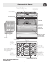
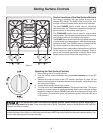
Sizes of the Surface Gas
Burners
Your appliance is supplied with the 4
different surface gas burners:
• 1 Simmer Burner (5,000 BTU)
• 1 or 2 Standard Burners (9,500 BTU)
• 1 Power Burner (12,000 BTU)
• 1 Power Burner (14,000 BTU)
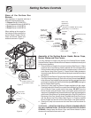
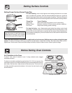
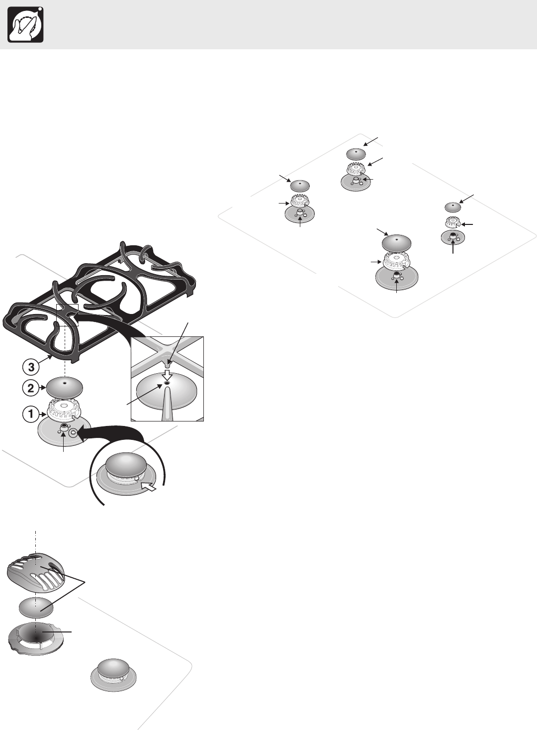
Assembly of the Surface Burner Heads, Burner Caps,
Burner Grates and Flue Covers
It is very important to make sure that all of the Surface Burner Heads,
Surface Burner Caps and Surface Burner Grates are installed correctly and
at the correct locations.
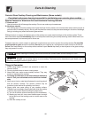
1. Place all 4 Burner Heads in the correct locations (See Figure 1). Make
sure that the correct Burner Head is placed with the corresponding
Orifice Holder and that the Electrode is located properly in the slot of
each Burner Head (See Figure 2). Proper Burner Head placement
insures that each Burner will have the correct spark required for surface
gas ignition.
2. Place the correct Burner Caps at each of the burner locations (Burner
Cap Pilot Hole must face up). Each of the 4 (four) Burner Heads MUST
have a Burner Cap installed to insure proper ignition and gas flame size
and must be in place with the Pilot Hole facing up BEFORE placing the
Burner Grates (See Figure 2).
3. Place the 2 (two) cast iron Burner Grates supplied with the range.
Carefully lineup the 2 Grate Pins on each Grate with the Cap Pilot Holes
in the 2 Burner Caps on each side of the range. DO NOT force the
Burner Grates onto the Burner Caps. Forcing the grates down onto
improperly installed Burner Heads and Burner Caps may damage the
gas burners. Each Burner Cap is designed with a Cap Pilot Hole in the
top center of the Cap. Visually check that ALL the Grate Pins line up
into the Burner Cap Pilot Holes (See Figure 2). Properly installed
Burner Grates will rest with all four Grate legs on the glass cooktop.
4. Place the 2 (two) flue covers over the inner vent cover as shown on
figure 3.
REMEMBER — DO NOT ALLOW SPILLS, FOOD, CLEANING AGENTS
OR ANY OTHER MATERIAL TO ENTER THE GAS ORIFICE HOLDER
OPENING. Always keep the Burner Caps and Burner Heads in place
whenever the surface burners are in use.
Figure 2
Grate
Pin
Burner
Grate
Burner
Cap
Burner
Head
Orifice
Holder
Cap Pilot
Hole
Electrode
Electrode must be
located properly in slot
of each Burner Head
Figure 3
Removable
Flue Covers
Inner Vent
Cover
Figure 1
Burner Cap
(Standard)
Standard
Burner Head
(9,500 BTU)
Left Front
Orifice Holder
Small Burner Cap
“SIMMER”
Burner Head
(5,000 BTU)
Right Rear
Orifice Holder
Extra Large
Burner Cap
Right Front
Orifice Holder
Left Rear
Orifice
Holder
Standard or “POWER” Burner Head
(9,500 BTU) or (12,000 BTU)
“POWER”
Burner Head
(12,000 BTU)
or (14,000 BTU)
Burner Cap
(Standard or
Extra Large)
When setting up the range for
the first time, make sure that the
correct Burner Heads, Burner
Caps and Burner Grates are
located as shown in Figure 1.