


8
30" DUAL FUEL SLIDE-IN RANGE INSTALLATION INSTRUCTIONS
(Models with an Electric Oven and a Gas Cooktop)
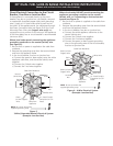
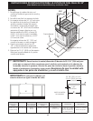
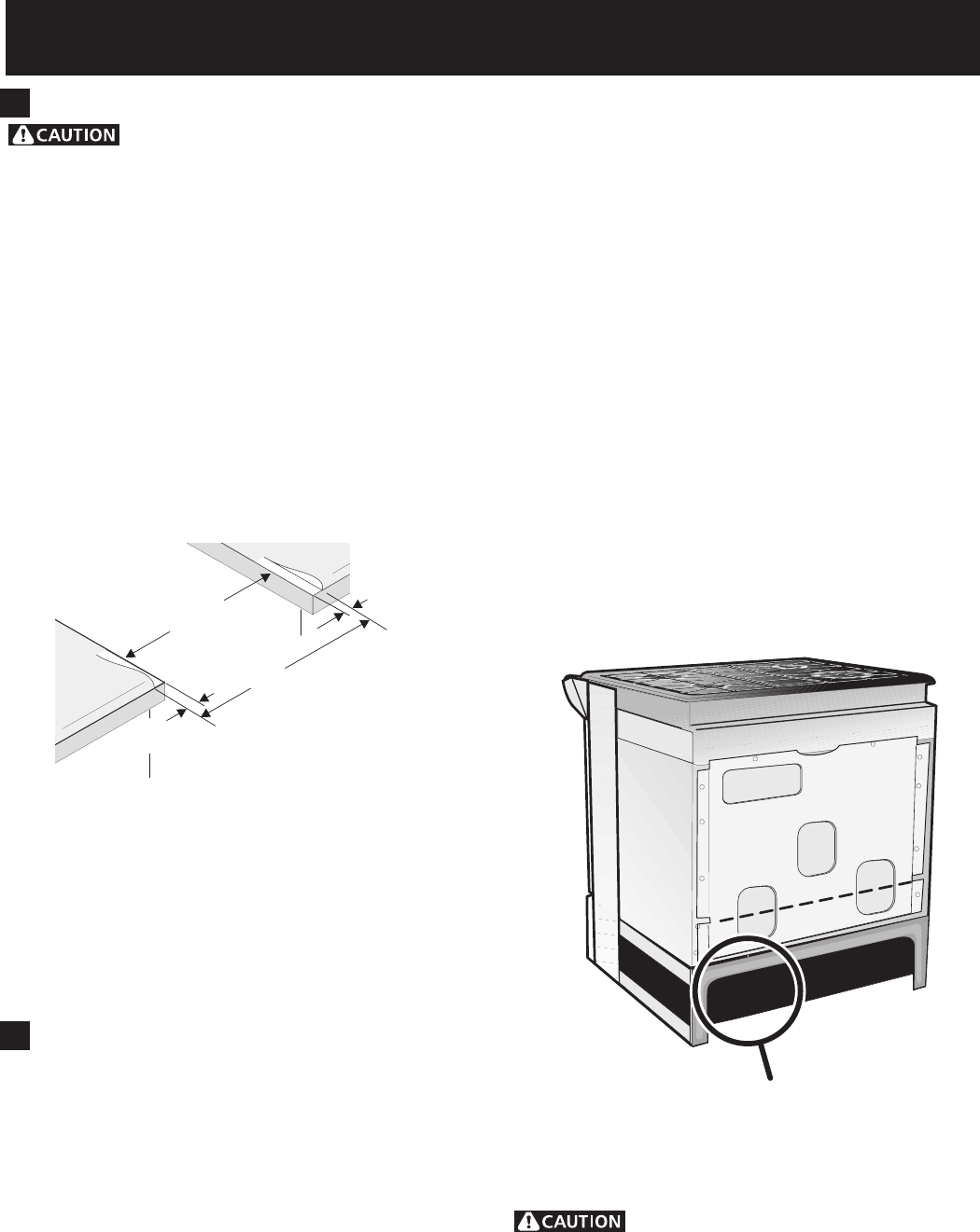
PRESSURE REGULATOR LOCATION
Figure 8
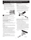
¾”
(1.9 cm)
¾”
(1.9 cm)
31½”
(81 cm)
Min.
Cutout
Width
Formed or tile countertop
trimmed ¾" (1.9 cm) back at
front corners of countertop
opening.
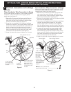
Figure 7
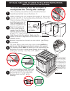
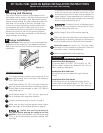
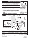
4. Cabinet Construction
To eliminate the risk of burns or fire by
reaching over heated surface units, do not have cabinet
storage space above the range. If there is cabinet
storage space above range, reduce risk by installing a
range hood that projects horizontally a minimum of 5"
(12.7 cm) beyond the bottom of the cabinet.
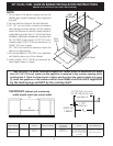
Countertop Preparation
•Thecooktopsidesoftherangetoverthecutout
edge of your countertop.
•Ifyouhaveasquare finish (flat) countertop, no
countertop preparation is required. Cooktop sides lay
directly on edge of countertop.
•Formedfront-edgedcountertopsmust have molded
edge shaved flat 3/4" (1.9 cm) from each front corner
of opening (Figure 7).
•Tilecountertops may need trim cut back 3/4"(1.9
cm) from each front corner and/or rounded edge
flattened (Figure 7).
•Iftheexistingcutoutwidthisgreaterthan
30 1/16" (76,4 cm), reduce the ¾" (1.9 cm)
dimension.
•Countertopmustbelevel. Place a level on the
countertop, first side to side, then front to back. If
the countertop is not level, the range will not be level.
The oven must be level for satisfactory baking results.
Cooktop sides of range fit over edges of countertop
opening.
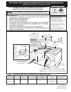
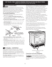
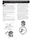
5. Gas Supply – Installation
When shipped from the factory, this unit is designed
to operate on 4"(10,16 cm) water column (1.0 kPa)
Natural gas manifold pressure. A convertible pressure
regulator is connected to the range manifold and MUST
be connected in series with the gas supply line. To access
the regulator, remove the drawer.
For proper operation, the maximum inlet pressure to
the regulator should be no more than 14"(35,56 cm) of
water column pressure (3.5 kPa).
The inlet pressure to the regulator must be at least 1"
(.25 kPa) greater than the regulator manifold pressure
setting. The regulator is set for 4"(10,16 cm) water
column (1.0 kPa) Natural gas manifold pressure; the inlet
pressure must be at least 5"(12.60 cm) water column
(1.25 kPa) Natural gas. For LP/Propane gas, the regulator
must be set for 10"(25,4 cm) water column (2.5 kPa)
manifold pressure; the inlet pressure must be at least
11"(27,9 cm) water column (2.75 kPa).
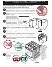
The supply line should be equipped with an approved
shutoff valve (see Figure 10). This valve should be located
in the same room as the range and should be in a
location that allows ease of opening and closing. Do not
block access to the shutoff valve. The valve is for turning
on or shutting off gas to the appliance. Open the shutoff
valve in the gas supply line. Wait a few minutes for gas
to move through the gas line.
The gas supply between the shutoff valve and the
regulator may be connected by rigid piping or by A.G.A./
C.G.A.-approved flexible metallic union-connected
piping where local codes permit use.
The gas supply piping can be through the side wall
of the right cabinet. The right side cabinet is an ideal
location for the main shutoff valve.
Connection to Pressure Regulator
The regulator is already installed on the appliance.
Do not make the connection too tight.
The regulator is die cast. Overtightening may crack the
regulator resulting in a gas leak and possible fire or
explosion.