


2-3
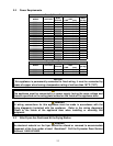
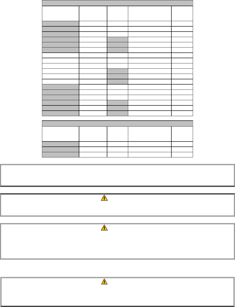
2.2 Power Requirements
Three (3) Phase Requirements
MODEL VOLTAGE
WIRE
SERVICE
MINIMUM WIRE
SIZE
AWG (mm)
AMPS
(per leg)
FPRE14 208 3 6 (4.11) 39
FPRE14 240 3 6 (4.11) 34
FPRE14 480 3 8 (2.59) 17
FPRE14 220/380 4 6 (4.11) 21
FPRE14 240/415 4 6 (4.11) 20
FPRE14 230/400 4 6 (4.11) 21
FPRE17 208 3 6 (4.11) 48
FPRE17 240 3 6 (4.11) 41
FPRE17 480 3 6 (4.11) 21
FPRE17 220/380 4 6 (4.11) 26
FPRE17 240/415 4 6 (4.11) 24
FPRE17 230/400 4 6 (4.11) 25
FPRE22 208 3 4 (5.19) 61
FPRE22 240 3 4 (5.19) 53
FPRE22 480 3 6 (4.11) 27
FPRE22 220/380 4 6 (4.11) 34
FPRE22 240/415 4 6 (4.11) 31
FPRE22 230/400 4 6 (4.11) 32
Single Phase Requirements
MODEL VOLTAGE
WIRE
SERVICE
MINIMUM WIRE
SIZE
AWG (mm)
AMPS
(per leg)
FPRE14 208 2 3 (5.83) 68
FPRE14 240 2 4 (5.19) 59
FPRE14 480 2 8 (3.26) 30
NOTICE
If this appliance is permanently connected to fixed wiring, it must be connected by
means of copper wires having a temperature rating of not less than 167°F (75°C).
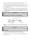
DANGER
This appliance must be connected to a power supply having the same voltage and
phase as specified on the rating plate located on the inside of the appliance door.
DANGER
All wiring connections for this appliance must be made in accordance with the
wiring diagram(s) furnished with the appliance. Refer to the wiring diagram(s)
affixed to the inside of the appliance door when installing or servicing this
equipment.
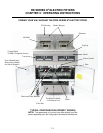
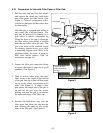
2.3 After Fryers Are Positioned At the Frying Station
DANGER
No structural material on the fryer should be altered or removed to accommodate
placement of the fryer under a hood. Questions? Call the Frymaster Dean Service
Hotline at 1-800-551-8633.