


4-3
4. Reinstall tube and bend it so that the opening is pointing downward.
4.3 Semi-Annual Checks and Service
Check Burner Manifold Pressure
WARNING
This task should be performed by qualified service personnel only.
WARNING
The frypot must be filled with water or cooking oil/shortening during this procedure.
1. Ensure that the gas valve knob is in the OFF position.
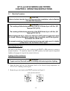
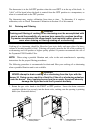
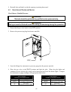
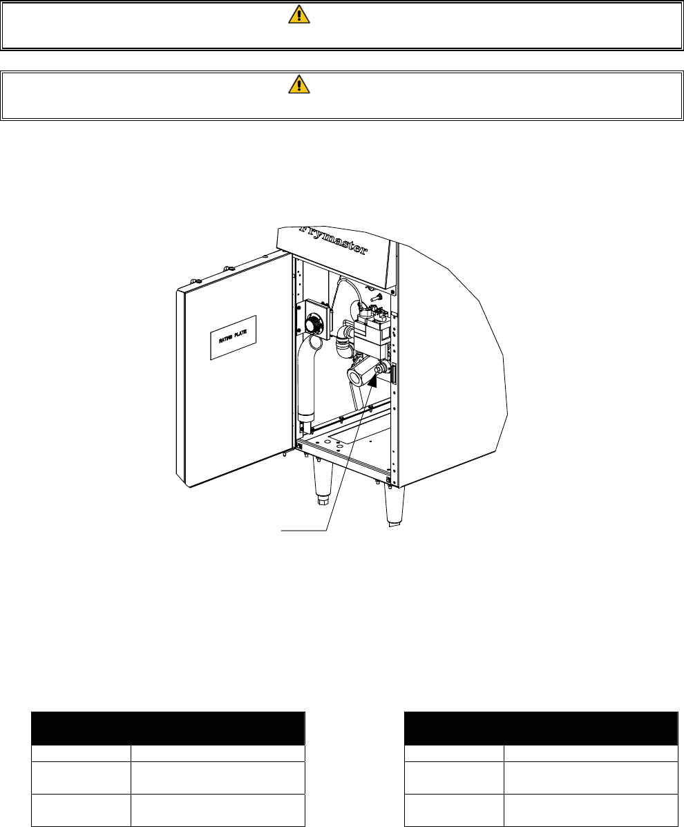
2. Remove the pressure tap plug from burner manifold.
Pressure
Tap Plug
3. Insert the fitting for a manometer or pressure gauge into the pressure tap hole.
4. Place the gas valve in the PILOT position and light the pilot. When the pilot lights and
continues to burn, increase the setting on the thermostat knob until the burner lights. Compare
the manometer or gauge reading to the appropriate table below.
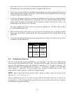
GF14 Standard
for Burner Manifold Pressure
Gas Type Pressure
Natural
4.0” WC
(1.00 kPa or 9.96 mbar)
LP
10.0” W.C
(2.49 kPa or 24.91 mbar)
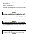
GF40 Standard
for Burner Manifold Pressure
Gas Type Pressure
Natural
3.5” WC
(0.87 kPa or 8.72 mbar)
LP
8.25” W.C.
(2.06 kPa or 20.55 mbar)