


1-21
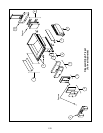
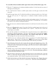
To re-assemble with new insulation and/or upper burner rails (use illustration on page 1-23):
13. Place the “L” shaped pieces of combustion chamber insulation (1) in the front and rear corners of
both upper rail-retaining slots.
14. Use a small amount of furnace or muffler repair cement to seal the gaps at each end of both
lower rails.
15. Install the upper burner rails (2) with the heat deflectors slanting toward the rear of the frypot.
The rails will cover the “L” shaped pieces of combustion chamber insulation previously
installed.
16. Place the upper inner combustion chamber insulation and insulation retainers (3) on the top two
studs on each side of the front of the frypot and secure with ¼”-20 washer-nuts. It is normal for
the retainers to slice off the overhanging insulation.
17. Place the lower rear combustion chamber insulation (4) on the lower four studs at the rear of the
frypot.
18. Place one 1.625-inch tubular spacer (5) on each of the flue assembly (upper) studs at the rear of
the frypot. NOTE: There are three different sizes of spacers. Verify the size to ensure the
correct spacers are installed.
19. Press the flue assembly (6) over the burner rails. It may be necessary to use a rubber mallet or
screwdriver to align the components. Use four ¼”-20 washer nuts to secure the flue assembly.
Do not tighten the retainer nuts at this point. They should be finger-tight only. NOTE:
The flue edge will cover one to two inches of the lower insulation.
20. Install the lower rear combustion chamber back(s) and retainer(s) (7) with the flanged edge(s)
against the flue. Secure with ¼”-20 washer nuts. NOTE: Full-vat units have two-piece backs
and four retainers. Dual-vat units come with one-piece backs and only two retainers.
21. Insert the burners (9) into the rails to ensure the rail spacing and alignment are correct. The
burner should slide freely into and out of the rails. The upper rail can be bent slightly to increase
or decrease tension on the burner and the edges of the slot can be closed or opened slightly to
best fit the burner frame.
22. Carefully wrap a strip of burner insulation (8) tightly around the rear and sides of the burner
frame (9), with the glass-tape side of the strip on the outside. Do not use duct tape or adhesive
to secure the strip to the burner frame.
23. Align the burner to the burner rails while maintaining tension on the insulation strip. Insert the
burner at a slight angle and begin pushing the burner slowly into the rails until it contacts the
rear combustion chamber. The fit should be snug, but not excessively tight.
24. Verify that the burners are flush with the front edge of the burner rails. Remove the excess
burner insulation by cutting with a knife or diagonal pliers. Do not try to tear the insulation!