


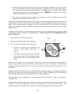
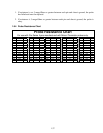
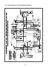

1-33
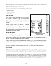
The following processes will assist you in troubleshooting the 24 VAC circuit and ruling it out as a
probable cause:
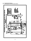
• 24 VAC is not present on the interface board J3 pin 9 (LED 5 (GV)) and, on dual units, on
J1 pin 9 (LED 1 (GV)).
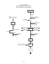
1. If LED 3 is not continually lit, the probable causes are a failed 24 VAC transformer or failed
wiring between transformer and interface board.
2. If LED 3 is continually lit, check the right PWR terminal (LED 4) for 24 VAC. On dual
units, also check the left PWR terminal (LED 2) for 24 VAC. Also verify that the F2 fuse is
good.
a. If 24 VAC is not present, the probable causes are a defective heat relay or a failed
interface board.
b. If 24 VAC is present, check for 24 VAC on V1S (or V1D and V2D, if dual unit).
i. If 24 VAC is not present, check the fuses. If they are good, the probable causes are
failed ignition module(s) or a failed interface board. Replace the questionable
ignition module with one known to be good to isolate the cause.
ii. If 24 VAC is present, the probable cause is a failed interface board.
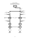
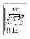
• 24 VAC is present on interface board J3 pin 9 (LED 5 (GV)) and, on dual units, on J1 pin 9
(LED 1 (GV)).
1. If 24 VAC is not present across the gas valve main coil (MV terminal), probable causes are
an open high-limit thermostat or a failed wire between the interface board and gas valve. Be
sure to check both valves on dual units. It may also be caused by a failed drain safety switch.
Check continuity of high-limit thermostat and drain safety switch. If both are zero, problem
is in wiring.
2. If 24 VAC is present across the gas valve main coil (MV terminal), the 24 VAC circuit is
working, and the problem may be with the gas valve. Be sure to check both valves on dual
units.