MASTER JET CF SERIES ATMOSPHERIC GAS FRYERS
CHAPTER 1: SERVICE PROCEDURES
1-29
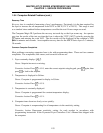
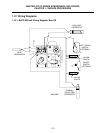
Optional ON-OFF switch
High-Limit
Thermostat
Operating
Thermostat
Pilot
Generator
FENWALL
Operating
Thermostat
HONEYWELL 1/2 P.S.I.
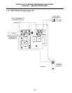
HONEYWELL
1/2 PSI
OFF
ON
PILOT
C
HONEYWELL
1/2 PSI
Pilot
Adj.
High-limit
Thermostat
Pilot
Generator
Safety Drain
Switch
ON/OFF Switch
(Optional)
17C
17C
12C
In Line Splice
In Line Splice
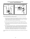
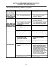
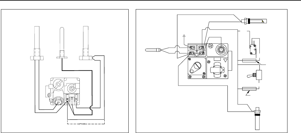
When troubleshooting millivolt systems, always check these areas before performing diagnostic
checks on either the Robertshaw or Honeywell systems:
A. Inspect all wires and component leads for damage (heat, oil, moisture, etc.). On capillary
tube-type thermostats, check for resistance on the thermostat lead wires. Wire nuts and other
connectors cannot be present in a millivolt circuit as they can cause resistance. If resistance
is found, solder the connectors to the wires or replace the wires.
B. Clean and verify that all wire connections and gas valve terminal connections are tight.
C. Check the length of the pilot flame (it should be about 1½-inches (38mm) long) and verify
that it contacts the top one third of the thermopile. Clean the pilot orifice and adjust the pilot
strength if needed.
D. Measure thermopile output with no load (i.e., with the thermopile disconnected from the gas
valve). Measurements must be made with a multimeter having a 0-1000 DC millivolt (MV)
range. Light the pilot and have someone hold the gas cock knob in the depressed position. If
the thermopile is a single lead (coaxial) type, measure from the lead’s end contact to its
screw-in threads. If the thermopile has two leads, measure across the end terminals. The
reading should be within the range of 500-800 millivolts. If not, replace the thermopile.
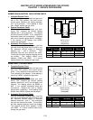
Performing diagnostic checks on Robertshaw and Honeywell Systems are described on the following
page.


