iv
Master Jet CF Series Atmospheric Gas Fryers
TABLE OF CONTENTS
PAGE #
1.
1.1
1.2
1.3
1.4
1.5
1.6
1.7
1.8
1.8.1
1.8.2
1.8.3
1.8.4
1.8.5
1.8.6
1.8.7
1.8.8
1.8.9
1.8.10
1.8.11
1.8.12
1.9
1.9.1
1.9.2
1.9.3
1.9.4
1.9.5
1.9.6
1.9.7
1.10
1.10.1
1.10.2
1.11
1.12
1.12.1
1.12.2
1.12.3
1.12.4
1.12.5
SERVICE PROCEDURES
Functional Description
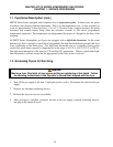
Accessing Fryers for Servicing
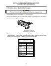
Cleaning Burner Manifold Gas Pressure
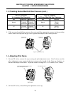
Adjusting Pilot Flame
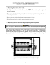
Cleaning Gas Valve Vent Tube
Adjusting Burner Ceramic Target Spacing and Alignment
Calibrating Thermostat Control
Replacing Fryer Components
Replacing Computer
Replacing Operating Thermostat
Replacing Temperature Probe
Replacing High-Limit Thermostat – Operating Thermostat Controls
Replacing High-Limit Thermostat – Computer Controls
Replacing Heat Mode Indicator Light – Operating Thermostat Controls
Replacing Power/Melt Cycle Switch – Operating Thermostat Controls
Replacing Melt Cycle Timer – Operating Thermostat Controls
Replacing Burner Ceramic Targets
Replacing Gas Valve
Replacing Pilot Assembly or Thermopile
Replacing Frypot
Troubleshooting and Problem Isolation
Pilot/Ignition Failures
Improper Burner Functioning
Improper Temperature Control
Computer Related Problems
Filtration Problems
Leakage Problems
Millivolt Problems
Troubleshooting Guides
Initial Troubleshooting, Millivolt Frying Systems
Initial Troubleshooting, 24VAC Frying Systems
Probe Resistance Chart
Wiring Diagrams
MJCF Millivolt Wiring Diagram, Non-CE
MJCF Millivolt Wiring Diagram, CE
MJCFE 24V Wiring Diagram
MJCFEC 24V Wiring Diagram
FAST-Ready Constant Pilot
1–1
1–1
1–4
1–5
1–6
1–7
1–7
1–8
1–9
1–9
1–10
1–11
1–11
1–12
1–13
1–13
1–14
1–15
1–17
1–17
1–18
1–20
1–20
1–22
1–23
1–24
1–26
1–28
1-28
1–31
1–31
1–33
1–34
1–32
1–35
1–36
1–37
1–38
1–39


