HEATED PASS THROUGH
INSTALLATION, OPERATION, SERVICE, AND PARTS
6
F. Cut the wire ties on the wiring bundle and, one at a time, disconnect the wires from the
failed assembly and connect the corresponding wire from the replacement motor.
G. Position the replacement motor over the mounting studs and secure it in place with the
5
⁄
16
-inch nuts removed in Step D.
H. Reinstall the blower bridge and secure it in place with the
5
⁄
16
-inch nuts removed in Step
C.
I. Apply new acrylic tape (P/N 811-1042) to the HPT chassis, then stand the plate on its
edge against the blower side of the unit.
J. Once the plate is properly aligned with the chassis, gently lower it into place.
K. Reconnect the plate ground wire to the push-on terminal on the back wall of the air
tower.
L. Inspect the gaskets on the bottom of the cowl assembly and air tower assembly for
damage. If necessary, remove the old gasket material, clean the surfaces thoroughly,
and apply new gaskets.
M. Slip the slotted brackets on the front section of the air tower assembly up and under the
nuts on the tower mounting screws. Push inward and down to ensure that the front
section is properly seated.
N. Check for gaps in the seal between the front section of the air tower assembly and the
plate. If a gap is present, remove the front section and apply a second gasket over the
one already in place and reseat the front section.
O. Once the front section is properly positioned and seated, tighten the nuts on the
mounting studs to pull it flush against the back of the tower assembly.
P. Carefully lower the cowl into position and check for a proper seal between the cowl and
the plate. Install another gasket over the one already in place if there are gaps between
the base of the cowl and the plate.
Q. Carefully turn the unit on its side and reinstall the five screws removed in Step B.
R. After the cowl is in place, reseal around the edges of the plate with RTV #108 silicone
rubber compound, P/N 811-0511.
6.5 Replacing Other Electronic Components
A. Disconnect the unit from the electrical power source.
B. Turn the unit on its side. Remove the five screws from the chassis bottom.
C. Set the unit down on its base.
D. Carefully lift the cowl assembly upward until it is clear of the blower assembly, then
lay it on the table behind unit.
E. If replacing any component other than the ON/OFF switch, hold the replacement
component next to the component to be replaced, disconnect the wires from the failed
component and connect them to the new component. When all connections have been
made, remove the failed component from its mounting and install the replacement
component.
F. If replacing the ON/OFF switch, disconnect the wiring and push the switch out of the
chassis. Press the replacement switch into the chassis and reconnect the wiring in
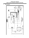
accordance with the wiring diagram.


