


Part # 1382650 Rev 4 (12/07) Page 7
INSTALLATION Continued
dealer. Installation must conform with the National Fuel Gas
Code ANSI Z223.1-1988 or latest edition, NFPA No. 54- Latest
Edition and National Electrical Code ANSI/NFPA 70-1990 or
latest edition and/or local code to assure safe and ecient
operation.
NOTE: The appliance and its individual shut-o valve (not
supplied by manufacturer) must be disconnected from
the gas supply piping system during any pressure testing
of that system at pressures in excess of ½ PSIG (3.45 KP2).
The appliance must be isolated from the gas supply piping
system by closing its individual manual shut-o (not
supplied by manufacturer) during any testing of the gas
supply piping system at test pressures equal to or less than
1/2 PSIG (3.45 KP2).
Installation for Ovens Equipped with Casters
A. The installation shall be made with a connector that
complies with the Standard for Connectors for Moveable
Gas Appliances, ANSI Z21.69/CSA 6.16, Addenda Z21.69B-
2006/CSA 6.16B-2006 (or latest edition), and a quick-
disconnect device that complies with the Standard for
Quick Disconnects for Use with Gas Fuel, ANSI Z21.41/
CSA 6.9, Addenda Z21.41A-2005/CSA 6.16A-2005 (or
latest edition).
B. The front casters of the unit are equipped with brakes
to limit the movement of the oven without depending
on the connector and any quick disconnect device or its
associated piping to limit the appliance movement.
C. Please be aware, required restraint is attached to the
bracket (which is located on the rear caster closes to the
gas connection), and if disconnection of the restraint is
necessary, be sure to reconnect the restraint after the
oven has been returned to its originally installed position.
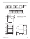
Installation for Ovens Equipped with Legs
Raise front of the unit and block. Do not lay unit on its back.
Position leg insert into leg retainer opening and tap up until
it seats at collar ange. Repeat at rear of unit making sure all
four legs are adjusted to same height. Legs can be adjusted
to overcome an uneven oor.
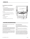
Ventilation and Air Supply
Proper ventilation is highly important for good operation.
The ideal method of ventilating a range is the use of a
properly designed canopy which should extend six inches
(6”) beyond all sides of the appliance and six feet (6’) six
inches (6”) from the oor.
A strong exhaust fan will create a vacuum in the room for an
exhaust system vent to work properly, replacement air must
enter the room in which the vent is located.
All gas burners and pilots need sucient air to operate and
large objects should not be placed in front of this oven which
would obstruct the air ow through the front.
Assembly of Battery
This section pertains to Master Series models only.
All heavy duty batteried equipment is aligned and tted at
the factory, from left to right and must be installed in this
order. There is a diagram provided with every heavy duty
battery.
A. All such units should be placed in their respective battery
position. Detach valve panels to prevent damage,
remove them from the area where the battery is being
assembled.
B. Level each unit (to the oven rack) by adjusting the six inch
(6”) legs (refer back to Item 1 for limitations), or where
legs are not used, adjust level with shims. Readjust legs, if
required.
C. Connect units together by mating the unions at each
end of the manifold. (Adjoining units must have
matching unions, unless the union parts are of the
same specications, a leak proof connection cannot be
assured.) Hand tighten unions at this point.
D. The units should be fastened at the rear by inserting
5/16” bolts through the holes provided at the rear of the
burner box sides. Be sure of proper unit alignment in the
battery before nal tightening of these bolts or unions.
Improper tightening will cause the “fanning” or “bowing”
of batteries units.
The nal tightening of the union should be accomplished
by using a suitable spanner wrench. If such a wrench is
not available, the Garland union collar has special ridges,
and a cold chisel can be driven against these ridges to
properly seat and seal the union.
E. The manifold of this unit or the manifold of which is
a part of must be equipped with a certied pressure
regulator suitable for battery application and adjustable
for an outlet pressure at the manifold as specied on the
rating place.