


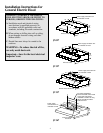
1. PREPARATION OF WALL CABINET
AND WALL
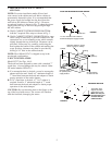
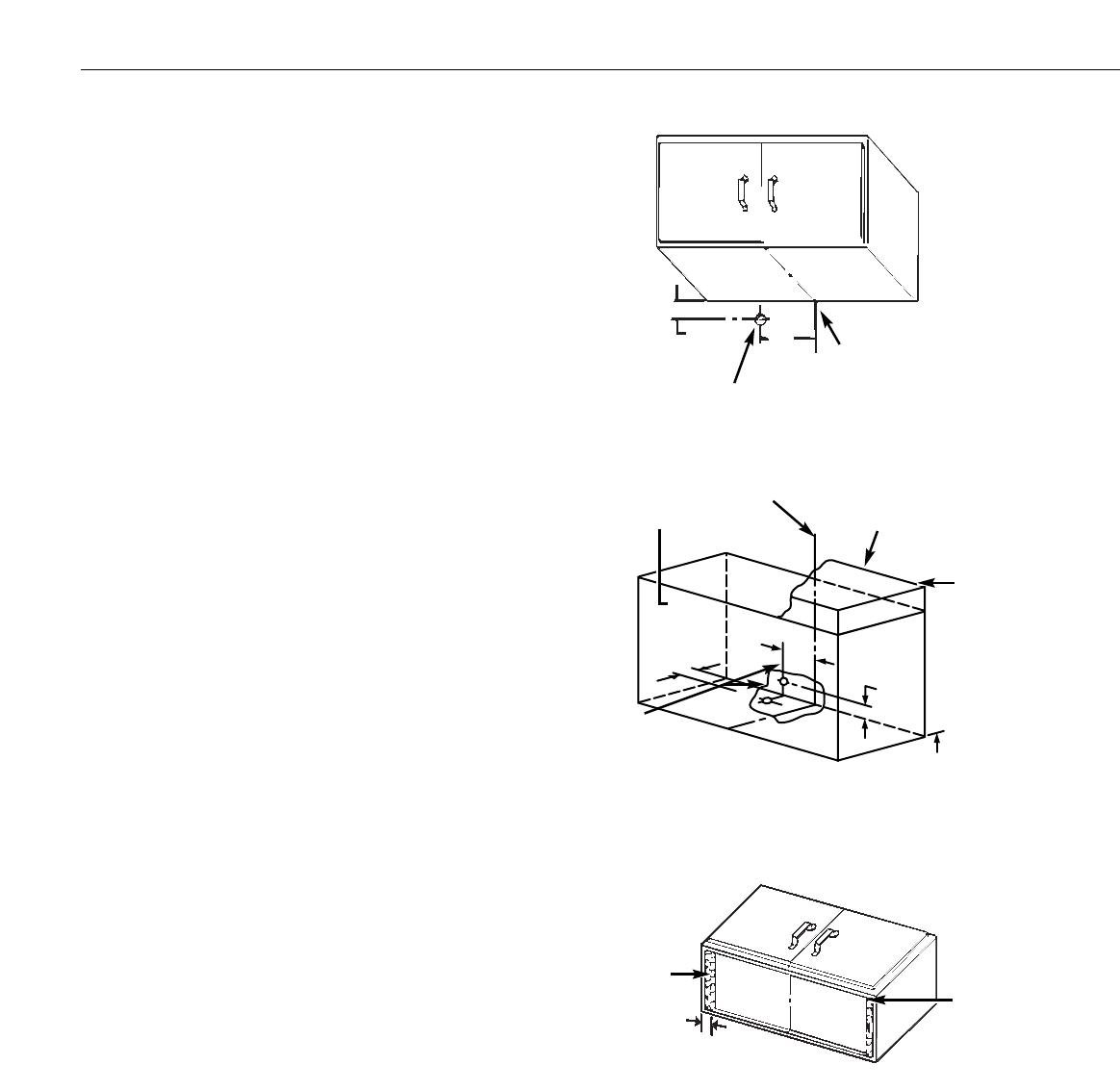
NOTE: For easier installation make all hood and
vent cutouts in the cabinet and wall before cabinet is
permanently fastened in place. It is recommended that
the power supply be brought into the hood from the
wall below the cabinet as shown in Fig.1. However,
an optional location is shown in Fig. 2, where the power
supply enters the top of the hood by passing through
the wall cabinet.
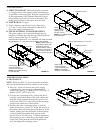
A. WALL CABINET WITH RECESSED BOTTOM:
Add the 2 required filler strips as shown in Fig. 3.
B. WALL CABINET WITH FLUSH BOTTOM: In some
cases it may be necessary to provide clearance for the
connection box cover mounting screw which extends
slightly through the top of the hood. Clearance can be
provided, if necessary, by carefully positioning the
hood against the bottom of the cabinet and marking the
screw position; clearance may then be provided by
drilling a 1/4″ hole in the cabinet bottom.
NOTE: Hood Model JV347 is shipped set up in the
non-ducted configuration.
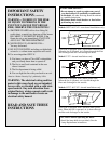
2. DUCT INSTALLATION
Model JV327 See Figs. 4 & 9
The hood has been designed to mate with a standard 7″
round duct. (A round damper kit may be ordered. Order
GE model number JXDA22.)*
A. If a rectangular duct is desired, a round to rectangular
adapter must be used. Install a 4″ minimum length of
7″ round duct between the hood and adapter to obtain
proper operation of the outlet damper.
B. If a 6″ round duct is desired, a 7″ to 6″ reducer is
required. Install a 4″ minimum length of 7″ round
duct between the hood and adapter to obtain proper
operation of the outlet damper.
CAUTION: Do not fasten the duct to the flange on the
top of the hood with screws. The screws will interfere
with the fan blade, damaging the motor.
5
RECESSED BOTTOM
FIGURE 3
Filler
strip
2
1
⁄2″ min.
These filler strips
support the entire
weight of the hood.
Make sure they are
mounted firmly and
are flush with the
cabinet bottom.
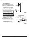
FLUSH OR RECESSED BOTTOM CABINET
FIGURE 1
1
1
⁄2″ dia. clearance hole in wall for
recommended power supply location
Centerline matches up with
center of range or cooktop.
1
1
⁄2″ dia.
clearance holes
for optional power
supply location
FIGURE 2
66″ from bottom
of cabinet to floor
1
1
⁄4″
7
3
⁄4″
1
1
⁄4″
Cabinet
Ceiling
1
1
⁄4″
7
3
⁄4″
Center line
Soffit
(optional)