


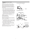
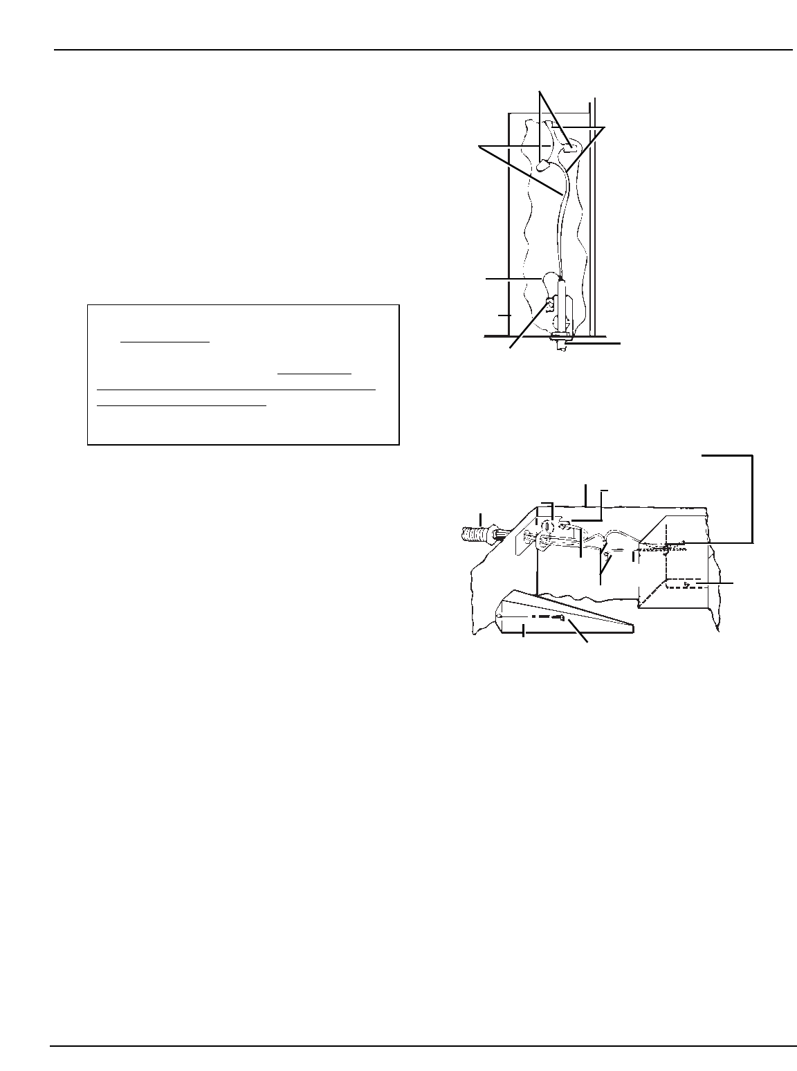
B. ELECTRICAL CONNECTION
1. Be sure the power supply is disconnected before
making electrical connections.
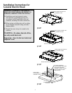
2. Remove the connection box cover located on the
left side of the fan unit.
3. Attach the power supply through the knockout hole
in the back or top of the hood.
4. Connect the colored incoming power supply
lead to the stripped black lead and connect the
incoming white neutral lead to the stripped white
lead in the connection box as shown in Figs. 12
and 13. Make connections in the hood in
accordance with local codes.
5. A ground lug is provided for proper grounding of the
hood frame. It is recommended that the hood frame
be grounded in accordance with National Electrical
Code and local codes (see Figs. 12 and 13).
6. All electrical connections should be inspected
carefully before the power is turned on to make
certain that none have come loose during shipment.
7. Reinstall the connection box cover.
8. Install a lamp (not supplied with hood in the socket).
(CAUTION: Maximum wattage on the lamp
should not exceed 60 watts.)
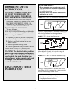
WARNING: IMPROPER CONNECTION
OF ALUMINUM
HOUSE WIRING TO
THESE COPPER LEADS CAN RESULT
IN A SERIOUS PROBLEM. USE ONL
Y
CONNECTORS DESIGNED FOR JOINING
COPPER TO ALUMINUM AND FOLLOW
THE MANUFACTURER’S RECOMMENDED
PROCEDURE CLOSELY.
8
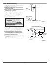
FIGURE 12
FIGURE 13
Top of hood
Cut off excess wire length so wires will
be easy to position under cover.
Knockout
plate
Power
supply
Power supply
connection
box cover
Mounting screw
Ground lug
(ground per para B3 colored leads)
Ground
(green)
lead
White
lead
Wire nuts
Connection
box cover
mounting
screw
Wire nuts
Power supply
Grounding lug
Ground
wire
Connection
box cover
White
leads
Colored leads