


INSTALLATION INSTRUCTIONS
STEP
4
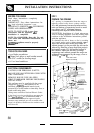
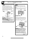
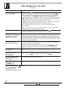
3 WIRE POWER CORD INSTALLATION
Remove the 3 wire terminal screws from
the connector block. Insert screws through
each power cord terminal ring and into the
connector block until the screws engage the
nuts. Be certain that the center wire is connected
to the center screw of the connector block.
Tighten screws securely. Do NOT remove
ground strap connection.
CONNECTOR
NEUT
K
TERM
D
POWER
W_ING:
THE NEUTRAL
OR GROUND
WIRE OF THE POWER CORD MUST BE
CONNEC133D
TO THE NEUTRAL
TERMINAL
LOCA’T’ED
IN THE CENTER OF
THE CONNECTOR
BLOCIL
THE POWER
LEADS MUST BE CONNECTED TO THE
OUTSIDE (BRASS COLORED) TERMINALS.
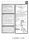
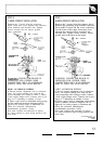
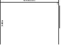
4
WIRE POWER CORD INSTALLATION
A. Remove the 3 screws from the connector
block.
B. Remove the grounding screw and strap from
the connector block middle location and the
screw connection to the frame of the range.
BEFORE
NEUTRAL
TERMINAL
;ROUNDING STRAP ‘
GROUNDING TO RANGE)
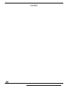
C. Insert screws through each power cord
terminal ring and into connector block until
screw engages nut. Be certain that the center
wire is connected to the center screw of the
connector block. Tighten screws securely.
D. Attach ground wire to the frame of the range.
AFTER
W-ING:
THE NEUTRAL
WIRE OF
SUPPLY CIRCUIT IS CONNECTED TO
THE NEUTRAL
TERMINAL LOCATED
IN THE CENTER
OF THE CONNECTOR
BLOCK. THE POWER LEADS MUST
BE CONNECTED TO THE OUTSIDE
(BRASS COLORED) TERMINALS. THE
4TH GROUNDING LEAD MUST BE
CONNECTED TO THE FRAME OF THE
RANGE WITH THE GROUNDING SCREW.
(continued
next page)
32