


– 17 –
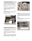
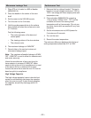
Primary Interlock System Test
WARNING: Disconnect the oven from the power
supply.
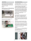
Door Sensing Switch
Isolate the switch and connect the ohmmeter to
the common (COM.) and normally open (NO)
terminal of the switch. The meter should indicate
an open circuit with the door open and a closed
circuit with the door closed.
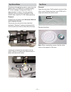
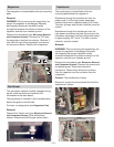
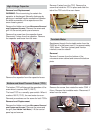
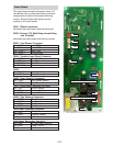
Power Relay
Disconnect 2 wires from the tab terminals on the
circuit board provided in the control panel
assembly. The tab terminals are located in the
area of the circuit board on the component side,
and are connected to the contacts of the power
relay. Check the state of the relay contacts using
an ohmmeter. The relay contacts should be open.
If the relay contacts are closed, replace the circuit
board.
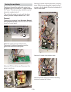
Primary Interlock Switch Test
Isolate the switch and connect the ohmmeter to
the common (COM.) and normally open (NO)
terminal of the switch. The meter should indicate
an open circuit with the door open and a closed
circuit with the door closed. If improper operation
is indicated, replace the primary interlock switch.
Note: The primary interlock switches are not
adjustable and must be replaced if test is failed.
Door Sensing Switch:
• Door Closed - 0 ohms
• Door Open - Infinite ohms
Monitor Interlock Switch:
• Door Closed - Infinite ohms
• Door Open - 0 ohms
Primary Interlock Switch:
• Door Closed - 0 ohms
• Door Open - Infinite ohms
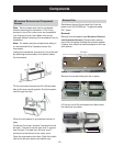
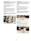
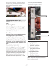
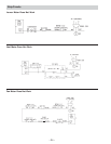
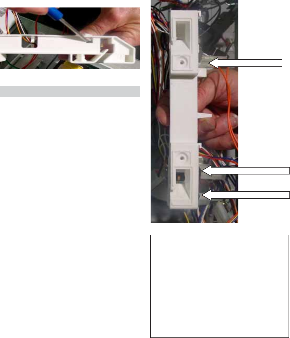
Interlocks (Door Latch Switches)
Interlocks are designed as follows:
Door Sensing Switch (top)
Monitor Interlock Switch (middle)
Primary Interlock Switch (bottom)
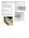
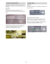
Note: Remove the wires from the switches
before checking continuity.
Using a small screwdriver, release the tab and
remove the door interlock switch from the door
switch bracket. Disconnect the electrical
connector.