Installation Instructions
FAUCET ASSEMBLY
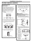
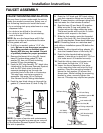
FAUCET MOUNTING INSTALLATION
Be sure there is room underneath the sink to
make the needed connections. Select one of
the following locations to install the faucet:
• In an existing sink spray attachment or soap
dispenser hole.
• In a hole to be drilled in the sink top.
• In a hole to be drilled in the countertop,
next to the sink.
NOTE: Be sure the faucet base will fit flat
against the surface at the selected location
so the gasket will seal.
1. If drilling is needed, make a 1-1/4″ dia.
hole. Be sure to use the proper procedure
for drilling porcelain or stainless steel.
Special drill bits may be needed. Consult
a qualified plumber for proper procedure.
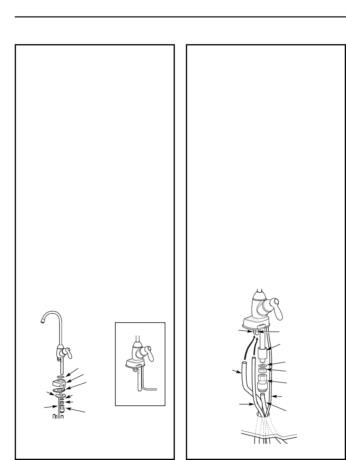
2. Remove the faucet, thin o-ring (D), faucet
base (E), bottom base gasket (F), lock
washer (G), hex nut (H) and mounting
bracket (I) from the packaging.
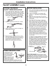
3. Feed the 3/8″ blue banded, 1/4″ black tube
(attached to the Reverse Osmosis System)
and the 3/8″ black tube (included in
separate packaging) up through the
mounting hole in the sink or countertop.
This step may require two people to
assemble. See page 14 for Optional
One Person Faucet Tubing Installation.
4. Feed the two black tubes up through the
gasket (F), faucet base (E) and O-ring (D).
NOTE: For ease of service and maintenance,
keep tubing lengths long enough so removal
of the Reverse Osmosis system from under
the sink is possible.
5. Push the 1/4″ black and 3/8″ black tubing
onto their respective fittings on the body (B).
NOTE: To ease insertion, submerge tubing ends
into hot water for a few minutes to soften.
6. Seat the base (E) and body (B) together.
Make sure the O-ring and gasket are
in place when the base meets the body.
The faucet handle will be at the 3 o’clock
position with respect to the base.
7. Slide the lock washer onto the threaded
stem of the body (B), then thread the hex
nut (H) onto the stem. Screw about halfway up.
NOTE: If installing faucet on a stainless steel
sink, slide on installation spacer (M) before the
lock washer.
8. Screw the blue tipped tubing adapter (K)
onto the threaded stem of the body (B).
9. Push the blue banded tubing into the
adapter. It should go in about 3/4″. Pull on
it to make sure it is installed correctly.
10. Feed the tubing, stem and power cord
back down through the 1-1/4″ hole.
11. Lower the faucet assembly into place
in the mounting hole and orient to final
position. Place the mounting bracket (I)
above the lock washer (G) around the
faucet stem. While holding the mounting
bracket in place, securely tighten the
hex nut. This step may require two people.
Mounting
bracket (I)
Base (E)
Hex nut (H)
Handle
Spout
Gasket (F)
Tubing
adapter (K)
Lock washer (G)
Power
cord (L)
O-ring (D)
Cap
ASSEMBLED
3/8″ barb fitting
3/8″ (black)
drain tubing
1/4″ (black)
drain tubing
1/4″ barb fitting
Tubing adapter (K)
3/8″ (blue banded)
outlet tubing
Hex Nut (H)
Lock washer (G)
Installation spacer (M)
(as needed)
Power cord (L)
Body (B)
From ROFrom ROTo drain
13


