


– 12 –
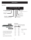
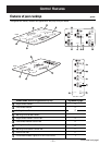
Operation Overview
DIGITAL CONTROL SYSTEM
The digital control system consists of 3 circuit boards:
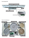
The touch board (permanently adhered to the ceramic glass panel) senses user input, including control
lockout, displays user settings, contains HOT lights and key touch beeper. It is the “Main” board for the
system.
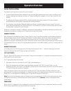
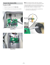
The relay power supply module (RPSM), located inside the drop box, provides DC for touch board
communications and to relays controlling the heating elements.
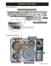
The daughter relay module (DRM) with additional relays is located under the touch board. The touch
board communicates with the RPSM board via 12-volt serial bus. The RPSM communicates with the DRM
via individual 5-volt and 12-volt DC levels.
There are no electronic sensors. Traditional-style sensors are located in the radiant elements providing over-
temperature protection cycling and HOT lamp input to the RPSM board.
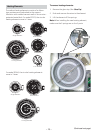
ELEMENT CONTROL
Each element is controlled by at least 2 relays. Both L1 and L2 are disconnected from the radiant elements
during standby (except the HOT lamp limiter switch). The setup relays remain constantly energized during
burner use. The cycle relays provide the duty cycling during non-HI settings. When non-Hi levels are
selected, the burners’ cycle relay will cycle 3 times per minute. When higher levels are selected, some cycling
of the element will occur due to the overtemperature limiter in the radiant element, which is in series with the
relays.
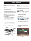
BURNER TOUCH KEYS
In standby, only the ON/OFF keys (and LOCK key) should respond. The +, –, and pan-size keys should not
respond until after the ON/OFF key has been touched fi rst.
HOT LIGHT CHECK
The HOT lights are LEDs within the touch board. They are commanded "on" via serial bus responses from the
RPSM board to the touch board.
A HOT light glows from two sources:
Whenever a burner is activated, the HOT light is immediately on.
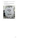
When the temperature of a ribbon heating element exceeds 150°F (66°C), the HOT light is on. At
temperatures over 150°F (66°C), the element's limiter switch closes, sending 240 VAC to the RPSM input at
J21 and initiating the serial bus response.
When the burner is cool to the touch and in standby, the HOT light should be off. When the burner is fi rst
activated, HOT should glow immediately. If a burner has been on for approximately 1 minute (5 minutes for
model JP975), then returned to standby, the HOT light should remain on until cool.
Note: Due to the low wattage rating, the warming zone surface element (JP975) will not glow red even when
on highest heat setting. The warming zone surface element (JP975) does not utilize an overtemperature
limiter switch.
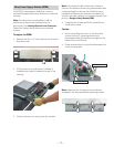
DEMO MODE
When 120 VAC is applied to the unit between the black and red leads, the touch board will operate normally,
but the relays and elements are prevented from operating.
1.
2.
3.
1.
2.