


Installation Instructions
11
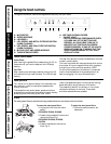
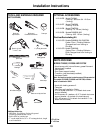
PARTS PROVIDED -
Continued
1 Ft = 0.3 m
1” = 2.5 cm
• Hood canopy with internal blower, grease filters and
lights already installed
• Glass vapour catcher
• Duct covers
• Duct Cover support bracket
• Transition (may be already installed)
• Hardware Packet:
Note: the hardware packet contains several fittings material.
For model PVWG936, consider what is listed below ONLY:
• Allen Wrench
• Lower support bracket x 2 (to attach the hood
canopy)
• Rubber tape (for glass vapour catcher)
• Bushes x 4 (for glass vapour catcher)
• 6 x 20 screws x 4 (for glass vapour catcher)
• Template
• Use, Care and Installation Guide
• 10 x 60 drywall anchors x 2 (To attach duct cover
support bracket)
• 6 x 80 screws x 6 + washers x 6 (2 To attach duct cover
support bracket + 4 to attach the hood canopy)
• 3,5 x 9,5 screws x 14 (2 to attach the transition + 4 to
attach the duct cover + 8 to attach the lower support
brackets)
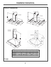
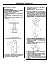
MODEL PVWG936
DUCTING OPTIONS AND EXAMPLES
Closely follow the instructions set out in this manual.
All responsibility, for any eventual inconveniences,
damages or fires caused by not complying with the
instructions in this manual, is declined.
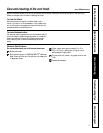
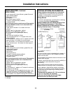
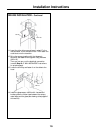
Venting Methods
The hood is equipped with a transition B for discharge
of fumes to the outside (Ducting version).
Models PVWS930/936 and PVWT936: Minimum Duct
Size (Ducting/Ductless version): 5" Round Pipe.
Models PVWG936 and PVIG940: Minimum Duct Size
(Ducting/Ductless version): 6" Round Pipe.
• Hood canopy with internal blower, grease filter and
lights already installed
• Glass vapour catcher
• Duct covers
• Chimney structure
• Transition (may be already installed)
• Use, Care and Installation Guide
• Hardware Packet:
Note: the hardware packet contains several fittings material.
For model PVIG940, consider what is listed below ONLY:
• Allen Wrench
• Rubber tape (for glass vapour catcher)
• Bushes x 4 (for glass vapour catcher)
• 6 x 20 screws x 4 (for glass vapour catcher)
• Template
• 6 x 80 screws x 4 + washers x 4(To attach the chimney
structure to the ceiling)
• 3,5 x 9,5 screws x 16 (8 to assemble the structure + 4 to
attach the duct covers + 2 to attach the transition + 2 to
attach the junction cover (may be already intsalled))
• 8 x 16 screws x 4 (to attach the canopy to the structure).
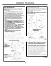
MODEL PVIG940
Ducted Version
Pipe
Pipe
Sidewall Cap
with Gravity
Damper
Pipe
Roof Pitch w/Flashing and Cap
Ducted Version
Roof Pitch w/Flashing and Cap
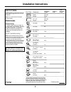
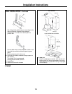
Preparation
Do not cut a joist or stud unless absolutely necessary. If
a joist or stud must be cut, then a supporting frame
must be constructed.
Fittings material is provided to secure the hood to most
types of walls/ceilings.
However, a qualified technician must verify suitability of
the materials in accordance with the type of
wall/ceiling.
Before making cutouts, make sure there is proper
clearance within the ceiling or wall for exhaust vent.
Hood installation height above cooktop is the users
preference. The lower the hood is above the cooktop,
the more efficient the capturing of cooking odors,
grease and smoke.
The hood shall be installed at 30" (76,2 cm) minimum
to 36" (91,4 cm) above the countertop.
Check your ceiling height and the hood height
maximum before you select your hood.
Models PVWS930/936, PVWT936
and PVWG936
Model PVIG940