


Installation Instructions
15
CEILING INSTALLATION
FOR MODEL PVIG940 ONLY
(For models PVWS930/936, PVWT936 and PVWG936
installation, please refer to paragraph
"WALL
INSTALLATION"
on previous pages).
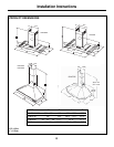
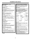
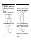
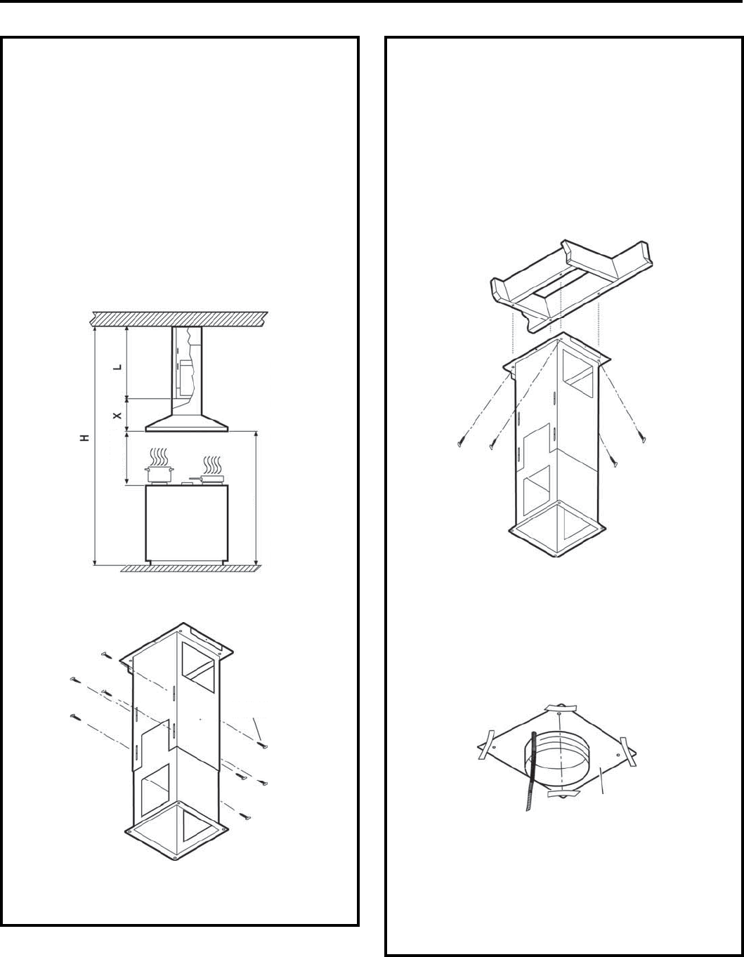
1. Choose the assembly height which is most convenient
for the user.
2. Measure the height “H” between the ceiling and the
floor
• establish the desired distance “D” between the floor
and the hood
• measure the height “X” of the hood
• you will obtain “L” by applying the following formula
L = H - (D + X).
D
min. 30” - 36”
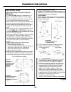
Once you have regulated the length of the telescopic
structure, fasten the two items using the 8 screws.
Ø 3.5 x 9.5
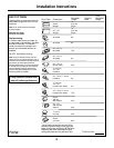
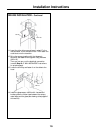
3. Mark the centre lines of the hob or the distance on the
overlying ceiling. Use the centre lines marked on the
ceiling to position the assembly template.
Note the position of the front part of the hood and
proceed with the installation.
Note:
All fastener location must span the studs
otherwise proceed as described in Step 4.
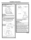
4. Remove the template and keep it. Cut the dry wall of
the ceiling and remove it. Install some wooden strips of
suitable length 2” x 4” between the joists to create the
assembly points of the chimney flue. Use the template
for the dimensions and to define the space required.
Make sure you fasten the wooden strips safely and level.
Consult a professional if you are having difficulty or if
this is your first installation.
5. Install the outlet duct. The female end should be 4½”
under the finished ceiling and fastened safely to the
joists. Do not use smaller ducts than those specified.
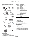
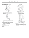
6. Install the conduit in the position marked in the hood
and measure out the length “L” from the ceiling (see
installation Step 2).
7. Install the dry wall around the duct and conduit then
proceed with the ceiling finish.
8. Fasten the outlet duct to the female end situated 4”
underneath the ceiling.
9. Position the telescopic structure adjusted previously.
Fasten it to the ceiling using the 4 screws. The outlet
duct and the conduit pass along inside it.
10. Insert the chimney with the grid facing the ceiling and
fasten it on the sides to the telescopic structure using
2 screws.
Template
1 Ft = 0.3 m
1” = 2.5 cm