


Installation Instructions
12
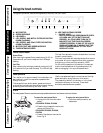
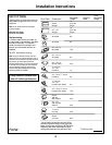
1 Ft = 0.3 m
1” = 2.5 cm
Models PVWS930/936 and
PVWT936
WALL INSTALLATION
FOR MODELS PVWS930, PVWS936, PVWT936 AND
PVWG936 ONLY
(For model PVIG940 installation, please refer to the
paragraph
"CEILING INSTALLATION"
on the next pages).
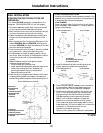
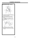
1. Choose the assembly height which is most convenient
for the user and mark the wall behind the hob.
2. Mark the centre line of the hood and trace the vertical
line from the bottom of the hood to the ceiling.
3. Fasten the template using adhesive tape, making sure
the centre line corresponds with the bottom of the
hood.
4. Mark the centre of the fixing points (6 fixing points for
models PVWS930/936 and PVWT936; 4 fixing points
for model PVWG936) through the template on the wall
and then remove the template.
5. Trace a horizontal line on the wall 1” above the highest
fixing point and 1” below the lowest fixing point.
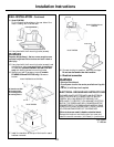
6. Find studs behind drywall by tapping wall or using a
stud finder. Mark the center of the studs with a vertical
line to the right and left of the marked fastener
location.
7.
Note:
All fastener location must span the studs
otherwise proceed as follows:
• Cutout drywall along marked lines.
• Install wood blocking between studs and make sure it
is flush with existing stud front. Make sure all
mounting screws will anchor to added studs.
• Replace drywall and refinish.
8. Mark the centre line again and the bottom of the hood
in same position as before and fasten the template to
the wall using adhesive tape as indicate above at point 3.
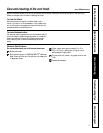
Ø 6 x 80
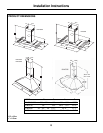
Models PVWS930/936 and PVWT936
A. Centerline
B. Mounting Hook
Location
C. Fastener Locations
D. Mounting Height
Reference
E. Template
Model PVWG936
A. Centerline
B. Mounting Hook Location
C. Fastener Locations
D. Mounting Height Reference
E. Template
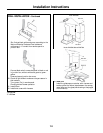
9.
Models PVWS930/936 and PVWT936:
Attach the 2 hooks with leveling screws (provided in the
assembly kit) to the points marked on the template with
2 screws and then remove the template.
Model PVWG936:
Screw 2 screws on lower fixing point but do not tighten
them completely (leave a space of ½") they will serve to
hang the hood canopy.
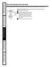
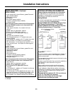
Models PVWS930/936 and
PVWT936
Model PVWG936
Ø 6 x 80
A. Centerline
B. Mounting Hooks (screws)
C. Fastener Locations
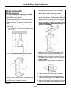
10. Install the bracket flush with the ceiling using the
drywall anchors provided with the appliance.
Model PVWG936
Ø 10 x 60
Ø 6 x 80
Ø 10 x 60
Ø 6 x 80
11. Determine and make all necessary cuts in the wall for
the vent system. Install the vent system before the
canopy hood. See „Venting methods“ paragraph.
12. Determine the required height for the conduit and
cut a 1¼" hole at this location. Run wires through
hole according to the National Electrical Code or
CSA Standards and local codes and ordinances.
Note:
If a In-line blower installation is required/
needed, then provide an additional hole/conduit.
There must be enough power supply cable from the
fused disconnect (Or circuit breaker) box to make the
connection in the hood’s Junction box/es.
Use caulking to seal all openings.
Do Not turn on power until installation is completed.