


18
ADJUST BURNER FLAMES
A. Turn all burners on highest setting and check the flames.
They should be blue (no yellow tipping) when using
natural gas. Foreign particles in the gas line may cause
an orange flame at first, but this will soon disappear.
B. Turn the cooktop burner knob to “LO” while observing
the flame.
Adjust the setting of the upper row of flames using the
valve bypass screw as follows:
Adjustments must be made with two other burners in
operation on a medium setting. This prevents the upper row
of flames from being set too low, resulting in the flame
being extinguished when other burners are turned on.
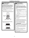
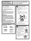
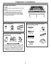
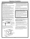
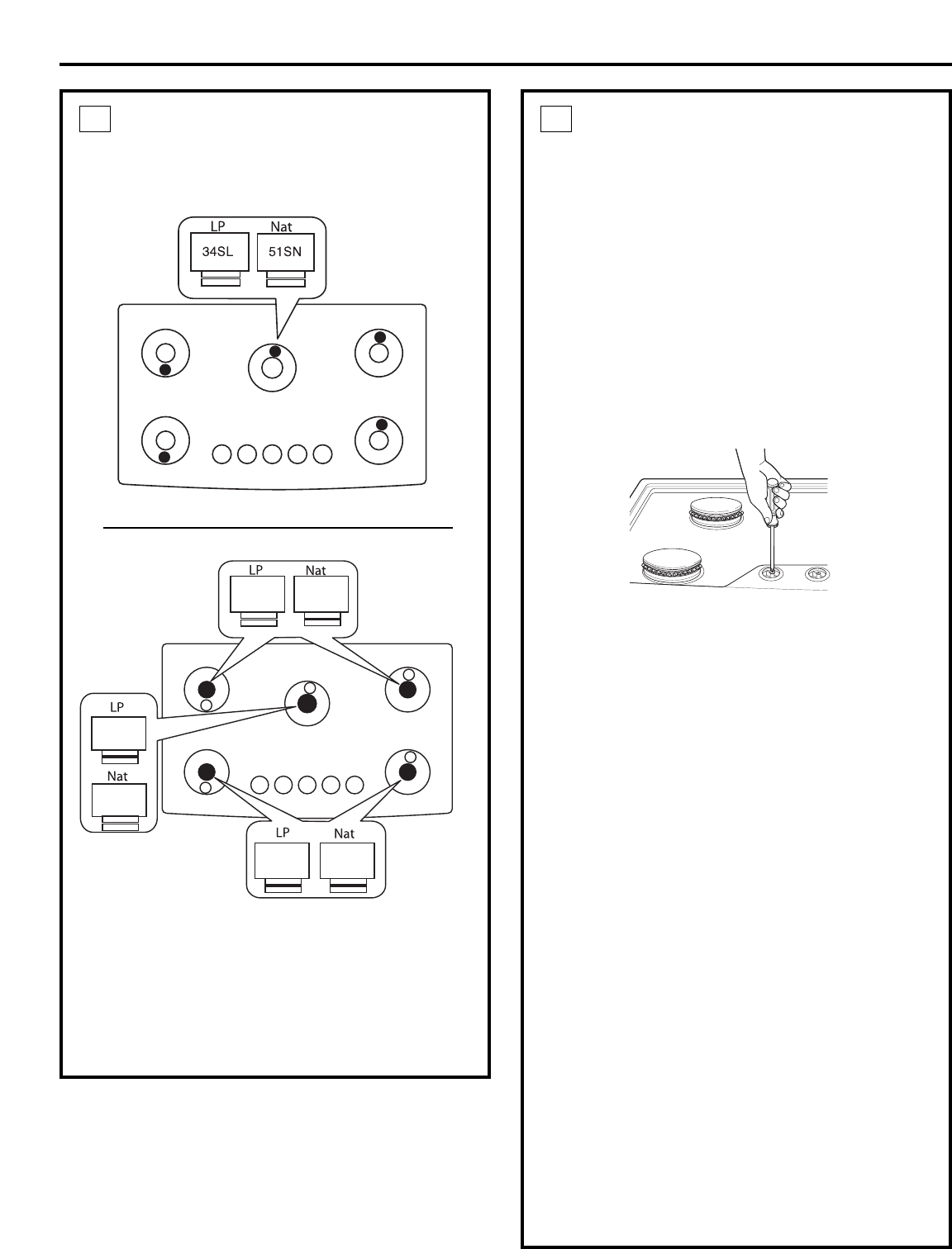
C. To adjust the flame, remove the knobs. Insert a
screwdriver through the access hole in valve shaft as
shown.
• If the flames were too small or fluttered, open the valve
more than the original setting.
• If the flames blew away from the burner, close the valve
more than the original setting.
D. Make the adjustment by slowly turning the screw until
flame appearance is correct.
E. Testing Flame Stability:
Test 1 – Turn the knob from “HI” to “LO” quickly.
If the upper row of flames goes out at this setting,
increase the flame size and test again.
Test 2 – With the burner on “LO”, open and close the
cabinet door under the cooktop. If the flame is
extinguished by the air currents created by the
door movement, increase the flame height and
test again.
NOTE: When the burner is on the “SIM” setting, the upper
row of flames will go out.
F. Flame Recheck:
After the adjustment is made, turn all burners off. Ignite
each burner individually. Observe the flame at the “HI”
position. Rotate the knob to the lowest setting and be
sure that the flame size decreases as the knob is
rotated counterclockwise.
Once the conversion is complete and checked ok,
fill out the conversion sticker and include your name,
organization and date conversion was made. Apply
the sticker near the cooktop gas inlet opening to
alert others in the future that this appliance has been
converted. If converting back to the original gas, please
remove the sticker so others know the appliance is set
to use its original gas.
3
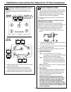
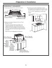
CHANGE BURNER ORIFICES (cont.)
IMPORTANT: Orifices must be located exactly as shown.
Carefully read and observe each orifice label for correct
location.
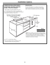
C. Install the proper orifices in the exact locations as noted
in the illustrations above.
D. Return the LP gas orifices to the bracket and reattach
the bracket and the instruction sheet to the pressure
regulator using the screw removed previously.
E. Replace the burner bases, heads, caps and top grates.
2
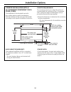
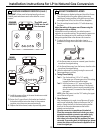
84XL
138XN
84XL
108XL
190XN
148XN
SIMMER
ORIFICES
MAIN
ORIFICES
Installation Instructions for LP to Natural Gas Conversion
The 34SL and
51SN are for all
five burners.