


POWER SUPPLY LOCATIONS
Gas supply:
These cooktops are shipped from the factory set
for either natural gas or LP gas. Check to be sure
you have the correct cooktop for the type of gas
being used.
• The pressure regulator must be connected in series
with the manifold of the cooktop and must remain
in series with the supply line regardless of type of
gas being used.
• The natural gas model is designed to operate at
5″ water column pressure. A regulator is required
at the natural gas source to provide a minimum
of 6″ water column to the cooktop regulator.
• The liquid propane model is designed to operate at
10″ water column pressure. A regulator is required
at the LP source to provide a minimum of 11″ water
column to the cooktop regulator.
• Maximum inlet pressure for the regulator supplied
with the cooktop is 14″ water column regardless of
the gas being used.
For ease of installation, and if local codes permit,
the gas supply line into the cooktop should be 1/2″
or 3/4″ ID flexible metal appliance connector, three
to five feet long.
NOTE: Purchase new flexible line. DO NOT USE OLD,
PREVIOUSLY USED FLEXIBLE LINE.
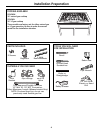
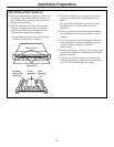
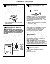
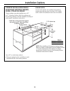
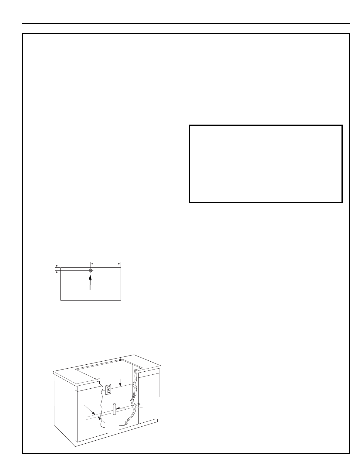
Rear–Burner Box
The gas inlet is
located on the
bottom of the
burner box at
the rear and
center.
• Make gas connection through rear wall, or on
cabinet floor at rear, as illustrated.
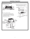
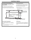
1. Install the house gas supply at least 1″ from
the back wall.
2. Locate the electrical outlet 12″ below the
countertop.
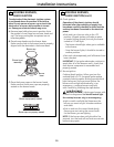
Install a manual shut-off valve in the gas line in an
easily accessible location outside the cooktop. Be
sure you know how and where to shut off the gas
supply to the cooktop. Install the electrical outlet
12″ below the countertop.
Electrical supply:
This cooktop features pilotless electric ignition for
energy savings and reliability. It operates on a 120 volt,
60 Hz power supply. A separate circuit, protected by a
15 amp time delay fuse or circuit breaker, is required.
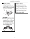
• A properly-grounded 3-prong receptacle should
be located within reach of the cooktop’s four-foot
power cord.
IMPORTANT: (Please read carefully). FOR PERSONAL
SAFETY, THIS APPLIANCE MUST BE PROPERLY
GROUNDED.
• The power cord of this appliance is equipped with
a three-prong (grounding) plug which mates with a
standard three-prong grounding wall receptacle to
minimize the possibility of electric shock hazard
from this appliance.
• The customer should have the wall receptacle and
circuit checked by a qualified electrician to make sure
the receptacle is properly grounded and has correct
polarity.
• Where a standard two-prong wall receptacle is
encountered, it is the personal responsibility and
obligation of the customer to have it replaced with
a properly grounded three-prong wall receptacle.
Do Not, Under Any Circumstances, Cut Or Remove
The Third (Ground) Prong From The Power Cord.
Do not use an extension cord.
Installation Preparation
8
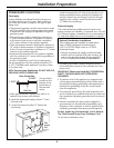
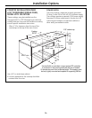
Optional Combination Installations
This cooktop may be installed in combination
with a ZVB36 Monogram Downdraft Vent,
a ZET1 or ZET938 Single Oven or a ZTD910
Warming Drawer.
• The gas and electrical supply must be located
where it will not interfere with vent housing, the
oven or the warming drawer. Review pages 12
to 14 for additional installation requirements.
1”
min.
12”
Gas
supply
line
1-15/16”
16-15/16”
Gas Inlet