


Design Guide
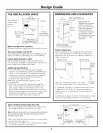
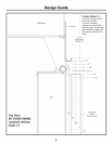
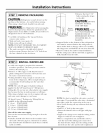
THE INSTALLATION SPACE
35-I/2"
FinishedWidth
The linished _1_ Wal,View
.to.t width/llg 2-8/1B''
mustbe /11 _T ,,
/ Im :8
maxL10
84-1/ ]] 75"From
83-1/2"min of ElectricalArea
Finished ]L_24" CutoutDepth ]] FloortoBottom
Opening I ] E
I 115' WaterSupply_
| ])¢) _:: (_
_' 31/2" 31/2" '
Water And Electrical Locations
Electrical and water suppl) must be located as shown.
The cutout depth must be 24"
The refrigerator will project forward, slighfl_ bexond
ac!iacent cabinetry, dei)ending, on _our installatilm.
Cutout depth beneath a soffit:
When installed beneath a soffit, the soffit cannot
exceed the 24" installation depth shown. The top case
trim overlaps the bottom of the soffit.
Additional Specifications
• A 115 volt 60Hz., 15 or 20 amp power supply is
required. An indMdual properly grounded branch
circuit or circuit breaker is recommended. Install
a properly grounded 3-prong electrical receptacle
recessed into the back wall. Electrical must be
located on rear wall as shown.
Note: GFI (ground tault interrupter) is not
recollllllended.
• Water line can enter the opening through the
floor or back wall. The water line should be 1/4"
O.D. copper tubing or GE SlnartConnect ''_kit
between the cold water line and water connection
location, long enough to extend to the fl'ont of the
refl'igerator. Installation of an easily accessible
sh ut-ott wflve in the water line is required.
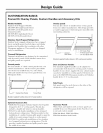
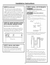
DIMENSIONS AND CLEARANCES
35" 25-3/4"FramedModels
CaseWidth 25-3/4"StainlessSteelModels
CaseOept,,
_Shippingheight.The
--'_ ] refrigerator can be adjustedto fit intoa cutoutthat is
_'84"From 83-1/2" min.to 84-1/2" max.
_83-1'2"1 _ I Floorto height.Notethatthetop
TopFrame casetrim at the frontis
36_Fr'd 1/2" higherandwill overlap
uppercabinetryorsoffit.
Uselevelinglegsandwheels
for amaximum1" height
adjustment.
" me to
FrameWidth
DepthIncludingHandles:
26-7/8"FramedModels
27-3/4"StainlessSteelModels
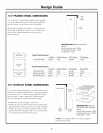
Product Clearances
These refrigerators are equipped with a 2-position
door stop. The factory set 130 ° door swing can be
a@Bted to 90 ° if clearance to a@_cent cabinets or
walls is restricted.
130° Door Swing
, 25"_
Minimum
to Wall
i
[,,,
130° ,
Allow 25" minimum clearance for a flfll
130 ° door swing. Allow 15" fl_r pan remoxal.
90° Door Swing
, ]13_,/8,,
] Behind
/ Frame
L_ '[
(
!36-3/4"
90° :j
4" Minimum
toWall
4" minimum clearance is required when door swing
is a(!justed to 90 °. If the 90 ° door stop position is
used, pan access is maintained, but pan removal is
restricted.
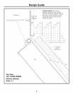
See illustrations pages 4 and 5 to deteHnine door swing
interaction with a@_cent cabinets or countertops.
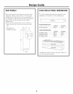
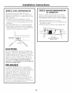
ZUG2, ZUGSS2 Unified Grille Panel Kit
• If you are installing two reli'igerators, side b_,side,
the installation space must be 71-1/2" wide.
Note:Additional cutout width may be required when side panels
are used. Addside panel thickness to the finished cutout to
calculate rough-in width.
• The water and electrical locations fl_r each product
mtlst be located as shown.
• A separate l ISV, 60Hz., 15 or 20 amp power supply
is recommended fin" each product.
-_71-1/2"FinishedWidth--
84-1/2"max
83-1/2"rain
Finished
Opening
.............................
_)6" ; F6"
10" 10"
24"Cutout
Depttl
WaterSupply_5
_-/ 26"_ _26 "_
3-1/2"
WallView
75"From
FloortoBottom
of ElectricalArea
3-1/2"
3