


16
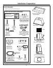
Installation Preparation
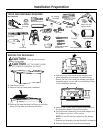
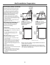
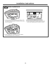
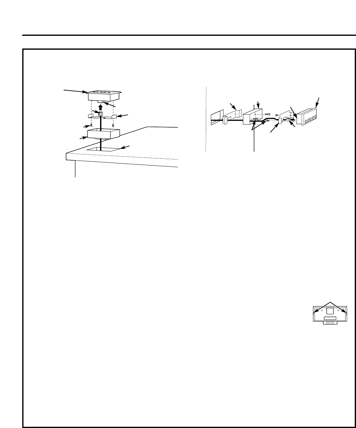
COUNTERTOP
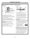
1. Cut out opening in the countertop. Cutout
dimensions are 1-11/16″ x 3-11/16″.
2. Loosen the 4 thumbscrews and remove the control
from the insert sleeve. Replace the control with the
blanking plate provided.
3. Attach the mounting plate to the back of the
control with the 2 mounting plate screws.
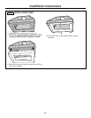
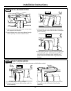
4. Pull the 4-wire cord through the opening in the
countertop, and through the back of the mounting
bracket.
NOTE: Use provided cables and connector/
converter ONLY.
5. Connect the 4-wire cord to the jack of the
connector on the remotely mounted control.
6. Press the control firmly into the mounting bracket
so that the clips engage.
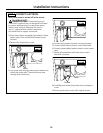
7. Apply silicone around the cutout opening.
8. Insert the control into the cutout opening.
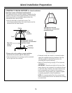
WALL MOUNT
1. Cut out opening into the wall surface. Cutout
dimensions are 1-11/16″ x 3-11/16″.
2. Loosen the 4 thumbscrews and remove the
control from the insert sleeve. Replace the
control with the blanking plate provided.
3. Attach the mounting plate to the back of the
control with the 2 mounting plate screws.
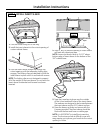
4. Pull the 4-wire cord through the opening in
the wall, the wall bracket and the back of the
mounting bracket.
NOTE: Use provided cables and connector/
converter ONLY.
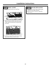
5. Connect the mounting bracket to the wall bracket
using the two wall bracket screws. Only start the
first 1–2 threads of the screws into the wall, as
you want to leave a gap between the two
brackets to account for the wall thickness.
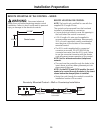
6. Raise the tabs on the mounting
bracket so the bracket will fit
through the wall opening.
7. Angle the mounting and wall
brackets and slide them through
the wall cutout.
NOTE: Attach a string to the brackets, so you can
retrieve them from behind the wall if dropped.
8. Flatten tabs on mounting bracket so they are
flush with the wall surface, and tighten the wall
bracket screws to pull the wall bracket flanges
flush with the backside surface of the wall.
9. Connect the 4-wire cord to the jack of the
connector on the remotely mounted control.
10. Press the control firmly into the mounting
bracket so that the clips engage.
4-wire cord
Mounting bracket
Screws
Connector
Apply silicone around
cutout opening
Mounting plate
Control
4-wire cord
Screws
Jack
Mounting
plate
Control
Wall
bracket
Mounting
bracket
Tabs
REMOTE MOUNTING OF THE CONTROL – WIRED (Continued)